
DSD-3.3-datapathcontrol
Datapath & Control
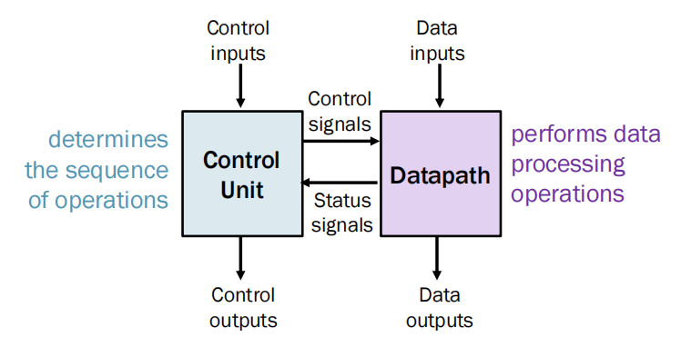
A real digital system incorporates both elements (i.e. datapath and control) working in unison
Datapath – provides status to control unit and makes decisions on next state.
Control unit – determines the sequence of operations.
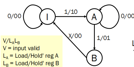
Data Flow Control
假如只有一条输入线路,通过register控制A B信号同时到达加法器

初始情况加法器输入输出都为?(不确定)
先让input输入A 加法器B的值等于A,A=?
下一个时钟输入B加法器A=A,B=B

取A+B的程序是:
初始条件
输入操作数A
将A存储到寄存器A中
输入操作数B
将B存储到寄存器B中
读取输出
将整个任务分解成更小的子任务,这些子任务可以在FSM中依次执行。
模块化、层次化设计:将系统划分为模块化子系统。
输入/输出
Datapath and Control Unit
– Datapath: data storage and processing
– Control unit: data flow and function selections
- There are three basic components in a datapath:
– set of registers in the system.
– operations performed on data stored.
– control that determines sequence of operations.
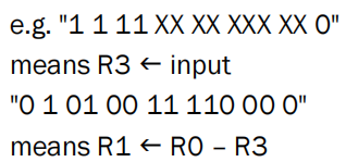
Register Transfers notation
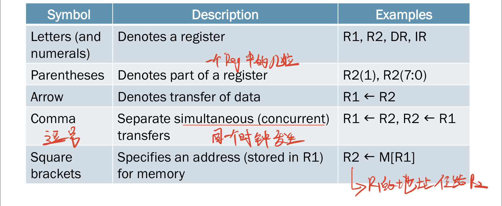
Register transfer notation (RTN) – notation which describes the datapath
寄存器传输表示法在描述数据路径时很有用。这种设计级别通常称为寄存器传输级别(RTL)。
从一个寄存器到另一个寄存器的数据传输使用替换运算符表示
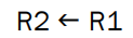

R2将被R1替代
布尔信号可以添加来创建条件传输,即数据传输依赖于控制信号:
K1是控制(使能信号)
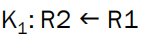
当K1=1时,且时钟到来时将R1传到R2
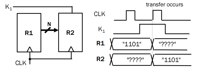
多个转移同时发生(一个时钟沿):
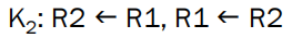
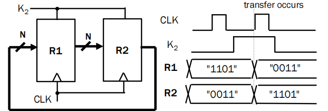
RTN的表示方法:
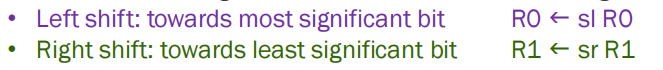
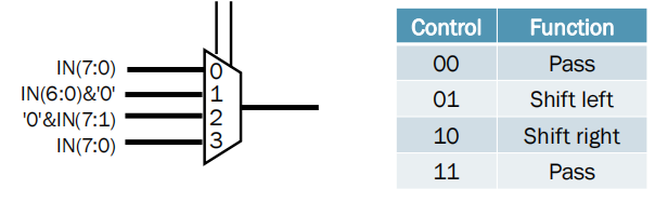
srR1 右移
slR1 左移
Micro-Operations
RTN中的运算符:微操作-对存储在寄存器或存储器中的数据进行的基本操作。
4 main types:
– Transfer: normal and conditional transfer
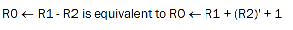
– Arithmetic: addition, subtraction
– Logic: AND, OR, XOR, NOT
– Shift: shift left (towards MSB), shift right (towards LSB)
如:

移动微操作用于数据的横向移动;寄存器的内容可以向左或向右移动。
这里使用组合逻辑的移位器
Datapath
数字系统可以分为datapath+control unite
数据路径——数字系统的数据所采用的路径
包含寄存器以及组合逻辑器件: ALUs, multipliers, dividers, shifters and rotators
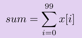
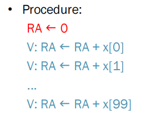
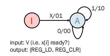
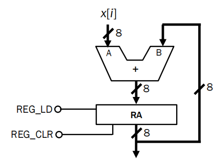
一个例子:Adding 100 integers in an array x[i] together
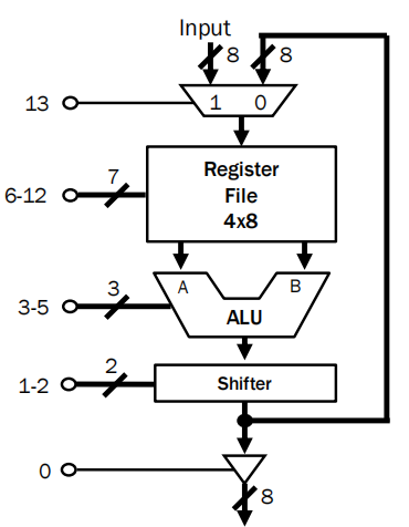
用datapath处理:
得到状态机:输入V为x[i]是否成功输入?
输出为load 和 clr
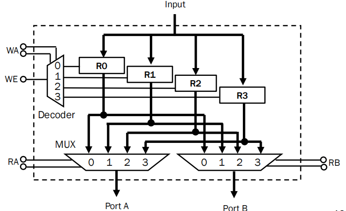
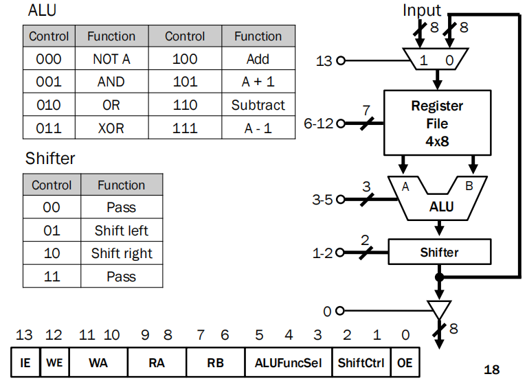
Register File:寄存器堆
Control signals are:
•write enable (WE) 写使能
• write address (WA) 写地址(往哪个寄存器里保存数据)
• read address A (RA) A端口输出哪个寄存器的数据
• read address B RB) B端口输出哪个寄存器的数据
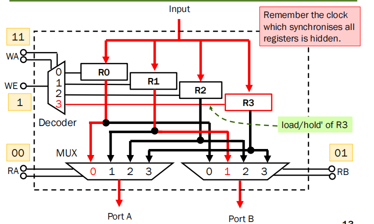
一个例子:把input存到R3,portA输出R0, PortB输出R1
注意这是个同步电路但是没画出时钟
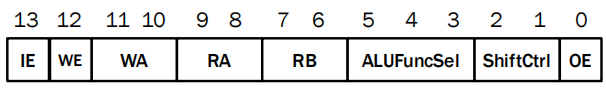
Control Word
当数据路径中有许多组合电路时,就会有大量的控制信号。
控制字:发送到数据路径块的控制信号的集合。
控制字包含控制单元为控制数据路径中的不同功能而必须生成的所有控制信号。
由于数字电路的传播延时,应该将时钟信号周期设置大于电路延时
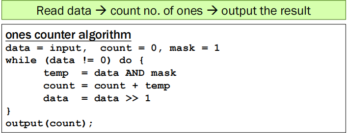
例子:Given a 8-bit binary number X, count the no. of ones in X找8bit 数据中有几个比特为1
在运算过程中最后的三态门都是高阻态,只有在最后需要输出时,才设为1(打开)
流程的伪代码:使用00000001与上data,如果input的最后一位是1就加一,否则不变,然后进行向右移位,直到data为0
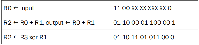
RTL/RTN:
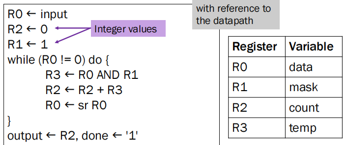
注意一个时钟只能处理一行
Control Words:
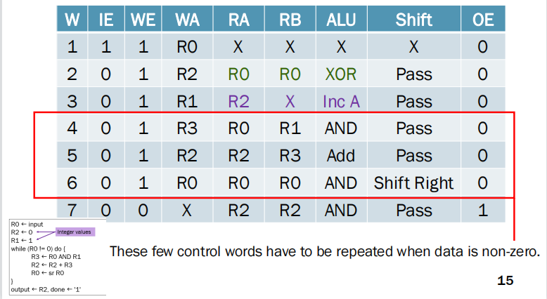
注意第二行和第三行:第二行使用R0 XOR R0产生0
第三行使用 R2自增产生1
循环红框中的control word直到最终input data 为0
要解决一个问题,我们可以先设计一个具有适当微操作的数据路径,并给出一个正确控制步骤和dataflow的FSM。