DSD-2.2-VHDL简介
VHDL简介
What can VHDL do?
VHDL can be used to model digital circuits and system.
Some type of circuit model allows simulation and/or testing of the circuit.
比起Graphical Approach来说,在面对有更多门电路时很方便
Synthesiser
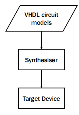
- VHDL is a hardware-design language.
When you are working with VHDL, you are not programming, you are “designing hardware”.
- Have a general concept of what your hardware should look like
If you don’t understand basic digital constructs (e.g. logic gates), you’ll probably fail to generate efficient digital circuits.
“Black-Box” Design Approach
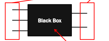
A VHDL module is considered as a black-box which has an entity and an architecture.
entity: the black-box itself input and output specification
entity给出ports的定义
architecture: the stuff that goes inside
architecture描述电路实现的功能
About VHDL
•VHDL is a specific language for describing hardware – digital circuits & systems.
• V = Very High-Speed Integrated Circuit (VHSIC)
HDL = Hardware Descriptive Language
Unlike other high computer languages, VHDL is NOT sequential in nature.
i.e. A; B; may have the meaning as B; A;
VHDL is a concurrent language(并发的 Concurrent)
VHDL instructions/statements are all executed at the same time.
VHDL describes hardware so actions are executed in a concurrent manner, i.e. in parallel
it has the ability to execute a virtually unlimited number of statements at the same time in a concurrent manner.
Basic Rules about VHDL
VHDL is not case senitive.
You can choose the case of your keywords and identifiers for readability.
Dout <= A and B; is the same as doUt <= a AnD b;
VHDL is not senitive to white space.
You should use spaces and tabs to well indent your VHDL
code.
nQ <= In_a or In_b; is the same as

nQ     <= in_a OR  in_b;
Comments
VHDL comments begins with the symbol (–).
there is no block-style comments in VHDL
Parentheses(括号)
if x = '0' and y = '0' or z = '1' then ...
if ( ((x = '0') and (y = '0')) or (z = '1') ) then
Every VHDL statement is terminated with a semicolon (;)
port (A, B: in std_logic; C: out std_logic);is actually considered a statement instead of a block
Identifiers
An identifier refers to the name given to items in VHDL
Examples of identifiers in VHDL include signal names, port names, variable names
• Identifiers should be self-describing.
• Identifiers can be as long as you want, it’s up to you.
• Identifiers can only contain a combination of letters (A-Z, a-z), digits (0-9) and the underscore (_).
• It must start with an alphabetic character
• It must not end with an underscore (e.g. xxyy_)
• It must not have two consecutive underscores (e.g. xx__yy)
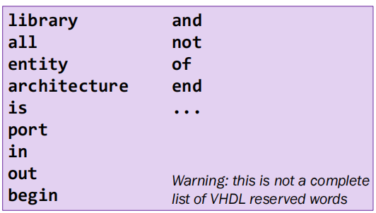
Reserved Words
You cannot use them as identifiers.
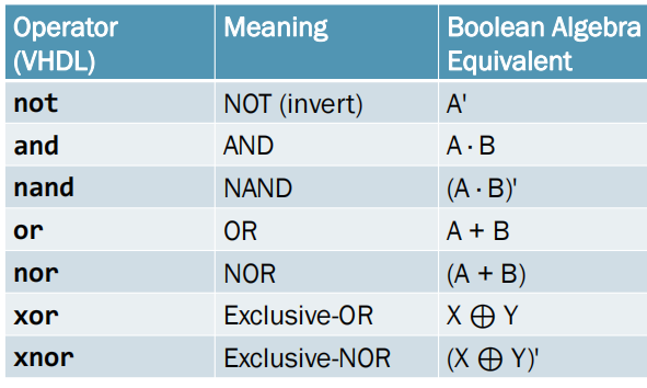
Logic Operator
Relational Operators

begin
F3 <= '1' when (L = '0' and M = '0' and N = '1') else
'1' when (L = '1' and M = '1') else
'0';
end f3_3;
Entity Declaration
• VHDL entity construct provides a method to abstract the functionality of a circuit description to a high level
The main usage of entity:
Interface - the list of signals from the underlying circuit(inputs and outputs )
wrapper: how the black box interfaces with the outside world (other black-boxes)
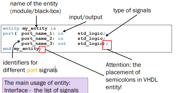
“–”表示注释
-- interface description of killer_ckt
entity killer_ckt is
port( life_in1: in std_logic;
life_in2: in std_logic;
ctrl_a, ctrl_b: in std_logic;
kill_a: out std_logic;
kill_b, kill_c: out std_logic);
end killer_ckt;
You can have several port names on the same line, separated by commas.(,隔开)
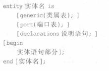
generic 语句
GENERIC(常数名 数据类型 := 设定值);
定义实体的端口大小;
设计实体的物理特征;
在例化时应该加generic map来修改不同需求下的元件例化参数
port语句:

- 端口模式:

- 数据类型:


BOOLEAN: 真假
INTEGER:32位整数
CHARACTER : 字符型
Architecture
The architecture describes what the circuit actually does.
there can be any number of equivalent architectures for the same single entity
同一entry可能有多种architecture
一个vhdl文件中可以存在多个architecture
connect Operator
可以将若干个标准逻辑类型或者逻辑向量首尾相接,描述成为一个新的逻辑向量。它的语法如下:
<signal 1> & <signal 2> &
该运算符尤其是在描述串行移位寄存器的时候最为方便,例如: d <= d(2 downto 0) & a;
Signal Assignment Operator
<= 表示 assignment
G <= A and B; --indicates the value of signal G represents an AND logic operation between A and B.<target> <= <expression>;Conditional Signal Assignment
WHEN/ELSE语句:
<target> <= <expression> when <condition> else
            <expression> when <condition> else
            <expression>;
each of the expressions associates with a condition
the conditions are evaluated until the first one is true, then the expression is assigned to the target
Only one assignment is applied per assignment statement.

With-select statement:
with <control> select
  <target> <= <expression> when <value>,
              <expression> when <value>,
              <value>;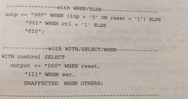
Intermediate Signals
• The declaration is similar that in entity, except that the mode specification (in/out) is not needed.
在architecture里声明中间信号而不是在entity
There is little (hardware) cost to pay when you use more Intermediate signals.
it is like an internal wire of the circuit, and it helps you to connect different parts of your circuit together.
Never judge the quality of a VHDL code by its length
exercise
- 与非门
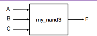
library IEEE;
use IEEE.std_logic_1164.all;
-- three-input NAND gate named my_nand3
entity my_nand3 is
port( A, B, C: in std_logic;
F : out std_logic);
end my_nand3;
-- behavioural architecture with logic operators
architecture my_nand3_arch of my_nand3 is
signal D: std_logic;
begin
D <= A and B and C;
F <= not D;
end my_nand3_arch;you must include libraries
operators: and, or, nand, nor, xor, xnor(binary) and not (unary)
Implement Boolean Equations using VHDL
Two ways:
(i) express the equation directly in a concurrent statement
(ii) sub-divide the equation into several parts and link them together using intermediate signals
F3 = L’M’N + LM
method (i):
architecture f3_2 of my_ckt_f3 is
begin
F3 <= ((not L) and (not M) and N) or (L and M);
end f3_2;
method (ii):
architecture f3_2 of my_ckt_f3 is
signal A1, A2: std_logic; -- intermediate signals
begin
A1 <= (not L) and (not M) and N;
A2 <= L and M;
F3 <= A1 or A2;
end f3_2;
Bus Signals
In VHDL, a bus signal can be specified by the vector data type,

std_logic_vector
When you declare a bus, you need to decide on the direction, whether the most significant bit (MSB)最高位 is on the left or on the right (assuming left-to-right writing).
On the left: downto; on the right: to
四选一数据选择器
-- a MUX that selects one of four bus lines for the output
entity mux4 is
port( a_data: in std_logic_vector(7 downto 0);
      b_data: in std_logic_vector(7 downto 0);
      c_data: in std_logic_vector(7 downto 0);
      d_data: in std_logic_vector(7 downto 0);
      sel1, sel0: in std_logic;
      data_out: out std_logic_vector(7 downto 0));
end mux4;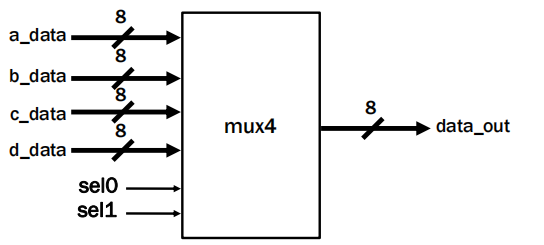
IEEE Standard Libraries
The data type std_logic and std_logic_vector is standardised by IEEE for the representation of digital signals.
In its generous definition, it is a nine-valued logic containing:
0, 1, U, X, Z, W, L, H, -.
导入1164库
library IEEE;
use IEEE.std_logic_1164.all;
...
VHDL Module
vhdl代码框架:
library IEEE;
use IEEE.std_logic_1164.all;
---- Descriptions about ----
---- your VHDL code ----
library IEEE;
use IEEE.std_logic_1164.all;
-- ENTITY --
entity module_name is
port( in1: in std_logic;
...
out1: out std_logic;
...); -- this is tricky
end module_name;
-- ARCHITECTURE --
architecture module_arch of module_name is
... -- DECLARATIONS
begin
... -- STATEMENTS
end module_arch;
the order that these statements appear in your VHDL source code makes no difference.
- exercise:
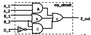
use IEEE.std_logic_1164.all;
entity my_circuit is
port( A_1, A_2, B_1, B_2, D_1: in std_logic;
E_out : out std_logic);
end my_circuit;
architecture my_circuit_arch of my_circuit is
signal A_out, B_out, C_out: std_logic;
begin
A_out <= A_1 and A_2;
B_out <= B_1 or B_2;
C_out <= (not D_1) and B_2;
E_out <= A_out or B_out or C_out;
end my_circuit_arch;
Modular Designs in VHDL
• Structural modeling allows modular designs.
• It also supports hierarchical design which is essential in complex digital systems.
packing low-level functionality into modules把低级的代码打包成模块,方便调用(easily reused in other designs as black boxes)-层次化
To further enhance module reuse, the VHDL modules can be placed in named files and libraries
元件例化,简单来说就是将以前设计的实体当做本设计的一个元件,然后利用VHDL语句将各元件之间的连接关系描述出来。元件例化语句由两部分组成,一部分是元件定义,即将现成的设计实体定义为本设计的元件。第2部分是元件连接关系映射,即描述各个元件之间的连接关系。
- declaration and instantiation of components:
Name the module you plan to describe (entity)
Describe what the module do (architecture)
Let the program know the module exists (declaration)
Use the module in your code (component instantiation or mapping)
以三位比较器为例
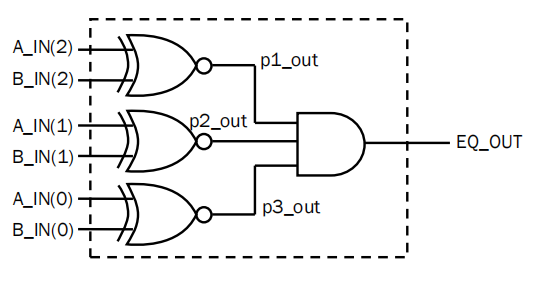
Step 1: Generate top-level entity declaration
entity my_compare is
port (A_IN : in std_logic_vector(2 downto 0);
B_IN : in std_logic_vector(2 downto 0);
EQ_OUT : out std_logic);
end my_compare;
Step 2: Declare the lower-level design units used
replace entity with component.
Place the component declarations before begin in the architecture.
放在architecture之前

Step 3: Declare internal signals
architecture structural of my_compare is
-- component declarations
component big_xnor is
port (A, B: in std_logic;
F : out std_logic);
end component;
component big_and3 is
port (A, B, C: in std_logic;
F : out std_logic);
end component;
-- internal signal declarations
signal p1_out, p2_out, p3_out: std_logic;
begin
...
end structural;
Step 4: Create instances of components and map
begin
    x1: big_xnor port map(A => A_IN(2), B => B_IN(2), F => p1_out);
    x2: big_xnor port map(A => A_IN(1), B => B_IN(1), F => p2_out);
    x3: big_xnor port map(A => A_IN(0), B => B_IN(0), F => p3_out);
    a1: big_and3 port map(A => p1_out, B => p2_out,
    C => p3_out, F => EQ_OUT);
end structural;
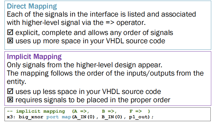
Mapping: make connections from higher-level signals onto the interface of the lower-level blocks. 将元件预定义的端口与实例化时的实际端口联系起来
Each of the individual mappings include a unique name of the particular instance plus the original entity.
--元件定义部分
COMPONENT 元件名 IS
	[GENERIC(类属表)];
	PORT(端口列表);
END COMPONENT 元件名;
--元件映射部分
例化名1:元件名1 PORT MAP(元件端口名=>连接端口名,...);
......
例化名n:元件名n PORT MAP(元件端口名=>连接端口名,...);
Labels should be always be added to increase the understandability of your VHDL model.
名称映射和位置映射
GENERATE
是一种可以建立重复结构或者是在多个模块的表示形式之间进行选择的语句。由于生成语句可以用来产生多个相同的结构,因此使用生成语句就可以避免多段相同结构的VHDL程序的重复书写。
标号:FOR 变量 IN 不连续区间 GENERATE
<并发处理的生成语句>
END GENERATE [标号名];
-- generation statement
generate_label:
for identifier in discrete_range generate
concurrent statements;
end generate generate_label;有两种用途:
- 生成相同的元件,多次例化;
MUX2_GEN: for i in 3 downto 0 generate
      L1: mux2 port map (D0(i), D1(i), shift_n(0), X0(i));
      L2: mux2 port map (X0(i), X1(i), shift_n(1), Y(i));
end generate MUX2_GEN;
同时例化四个MUX
- 生成结构相同的多次赋值、组合逻辑;
FOR i IN 0 TO 99 GENERATE

a(i)<=b(i)+c(i);

END GENERATE;
Standard Models in VHDL
There are different standard models/approaches in writing VHDL architectures.

More complicated VHDL circuits usually use a mixture of the three styles.
Data-Flow Style Architecture
Data-flow style: circuits are described by showing input and output relationships between the various built-in components.

Behavioural Style Architecture
行为建模
it is fairly straight forward to imagine the underlying circuitry in dataflow style

• provides no/fewer details as to how the design is implemented in actual hardware.
• models how the circuit outputs react to the circuit inputs.
只处理电路对输出的反应,而不用研究具体的电路细节
• allows you to leave the implementation details to the synthesizer
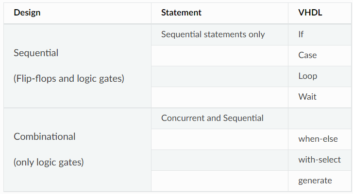
sequential circuit 只能用 behavioural modeling
combination circuit 可以用 behavioural modeling和 flow data behavioural
Process Statement
A process statement is a concurrent statement identified by its label, its sensitivity list, a declaration area and the set of instructions
-- this is my first process
my_label: process(sensitivity_list) [is][] - optional
    <item declaration>
begin
    <sequential_statements>
end process my_label;
Major difference: the statements inside a process are executed and interpreted sequentially
entity my_xor is
port ( A, B : in std_logic;
       F : out std_logic);
end my_xor;
architecture dataflow of my_xor is
begin
    F <= A xor B;
end dataflow;
architecture behav of my_xor is
begin
xor_proc: process (A, B)
begin
F <= A xor B
end process xor_proc;
end behav;
这两种代码形式是等价的
A B是敏感信号,所以一旦有一个改变 process就会执行。
For the behavioral architecture description, any time there is a change in signals in the process sensitivity list, all of the sequential statements in the process are re-evaluated until the end of the process body.
But the whole process itself is a concurrent statement
process 之间是并发关系
写VHDL时可以将预期功能分成不同进程来写,避免一个大进程

IF statement
The if statement creates a branch in the execution flow of the sequential statements.
if (condition) then
    <statements>
elsif (condition) then
       <statements>
else
       <statements>
end if;
The parentheses around the condition are optional .Use them for improving readability
The final else clause, which serves as a catch-all statement, is optional, but should always be included.
example

architecture silly_example of my_ex is
begin
    proc1: process (A, B, C)
    begin
        if (A = '1' and B = '0' and C = '0') then
            F_OUT <= '1';
        elsif (B = '1' and C = '1') then
               F_OUT <= '1';
        else
               F_OUT <= '0';
        end if;
      end process proc1;
end silly_example;
A process label is a form of self-description, which should be meaningful and easy-to-understand.


8-to-1 MUX Example
entity mux_8t1 is
port ( DIN: in std_logic_vector(7 downto 0);
       SEL: in std_logic_vector(2 downto 0);
       F : out std_logic);
end mux_8t1;
architecture mux_8t1_arch of mux_8t1 is
begin
    my_mux: process (DIN, SEL)
    begin
        if (SEL = "111") then F <= DIN(7);
        elsif (SEL = "110") then F <= DIN(6);
        ...
        elsif (SEL = "000") then F <= DIN(0);
        else F <= '0';
        end if;
    end process my_mux;
end mux_8t1_arch;
Case Statement
case (expression) is
    when choices =>
         <statements>
    when choices =>
         <statements>
    when others =>
         <statements>
end case;
Only one set of sequential statements is executed, depending with when branch is evaluated as true.
example

architecture case_ex of my_ex is
    signal INPUT: std_logic_vector(2 downto 0);
begin
    INPUT <= A & B & C;
    proc1: process (INPUT)
    begin
        case (INPUT) is
        when "100" => F_OUT <= '1';
        when "011" => F_OUT <= '1';
        when "111" => F_OUT <= '1';
        when others => F_OUT <= '0';
        end case;
    end process proc1;
end case_ex;
Simulation & Test Benches
After we model a circuit, we have to verify the correctness of the model in terms of functionality and timing
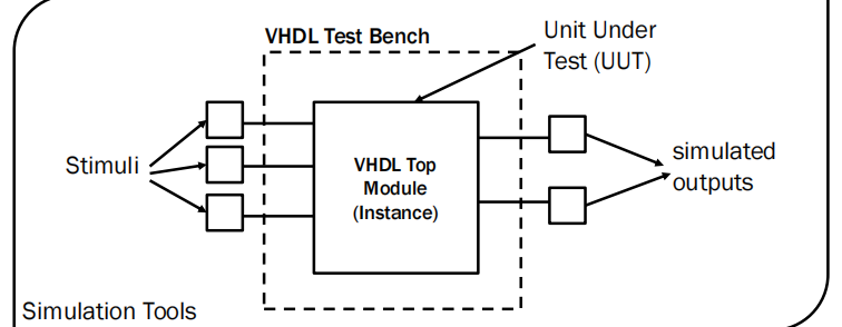
Simulation tools often require a test bench file to specify how the testing is done on the Unit Under Test (UUT)被测单元.
A VHDL test bench is virtual circuit/system that creates an instance of the
top module (UUT) and generates stimuli to inputs of the instance.
Corresponding simulation outputs are recorded and visualised to assist verification.
The test bench itself is not involved in implementation (not synthesisable)
Example
If we are to test the XNOR gate, then we can prepare a test bench like this:
A test bench is a closed system: no inputs/outputs.
Declare the UUT component and internal signals
entity big_xnor_tb is
end big_xnor_tb;
architecture behavior of big_xnor_tb is
    component big_xnor is
    port (A, B: in std_logic;
          F : out std_logic);
    end component;
    signal A, B, F: std_logic;
begin
    uut: big_xnor port map (A=>A, B=>B, F=>F);
    stim_proc: process
    begin
        A <= '0'; B <= '0'; wait for 10 ns;
        A <= '0'; B <= '1'; wait for 10 ns;
        A <= '1'; B <= '0'; wait for 10 ns;
        A <= '1'; B <= '1'; wait for 10 ns;
        wait; -- finished.
    end process;
end behavior;
Clock Signal
entity DFF_tb is
end DFF_tb;
architecture behavior of DFF_tb is
    component DFF is
    port (D, CLK: in std_logic;
          Q : out std_logic);
    end component;
    signal D, CLK, Q: std_logic := '0';
    constant period: TIME := 10 ns;--时间常数
begin
    uut: DFF port map (D=>D, CLK=>CLK, Q=>Q);
    stim_clk: process
    begin
        CLK <= '1'; wait for (period / 2);
        CLK <= '0'; wait for (period / 2);
    end process;
    stim_proc: process
    begin -- add your stimuli
    end process;
end behavior;
initial values given using operator :=
信号初始值要用:=
type 类型
TYPE 数据类型名 IS {枚举1,枚举2,…}
type state_type is **(ST0,**ST1);


