DSD-3.2- verilog
Verilog
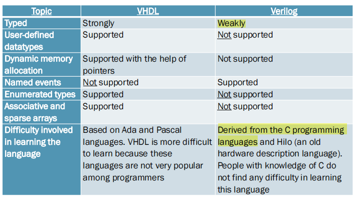
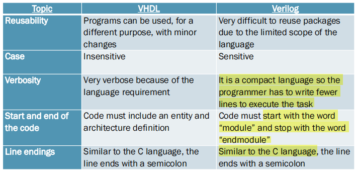
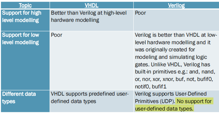
difference between VHDL and Verilog
数据类型
Verilog中2 种数据类型就是线网(wire)与寄存器(reg)
线网(wire)
带有延时的线网:
wire #3 x2; #3:对x2的所有赋值操作都会延时三个单位
wire #(3,5) x2; 对x2赋值1时时延3,赋值0时时延5
寄存器(reg)
寄存器(reg)用来表示存储单元,它会保持数据原有的值,直到被改写。声明举例如下:
reg   clk_temp;
reg  flag1, flag2 ;
Logical Gate
vhdl
entity andGate is
port(A : in std_logic; -- AND gate input
B : in std_logic; -- AND gate input
Y : out std_logic); -- AND gate output
end andGate;
architecture andLogic of andGate is
begin
Y <= A AND B;
end andLogic;
Verilog
module AND_2(output Y, input A, B);
and(Y, A, B);
endmodule;
Comparison
Verilog 是区分大小写的。
必须以 module开始以endmodule结束
Comparator
vhdl
architecture dataflow of comp_4 is
begin
process(A, B)
begin
if (A = B) then
output <= "0011";
elsif (A > B) then
output <= "1111";
else
output <= "0000";
end if;
end process;
end dataflow;
12
Verilog
module mag_comp (A, B, ALTB, AGTB, AEQB);
input [3:0] A, B;
output ALTB, AGTB, AEQB;
assign ALTB = (A < B),
AGTB = (A > B),
AEQB = (A == B);
endmodule
if A<B is true, we assign a “1” to ALTB
连续赋值语句是 Verilog 数据流建模的基本语句,用于对 wire 型变量进行赋值。:
格式如下
assign LHS_target = RHS_expression ;- LHS_target 必须是一个标量或者线型向量,而不能是寄存器类型。
- RHS_expression 的类型没有要求,可以是标量或线型或存器向量,也可以是函数调用
Half adder
vhdl
entity half_adder is
port (
i_bit1 : in std_logic;
i_bit2 : in std_logic;
--
o_sum : out std_logic;
o_carry : out std_logic
);
end half_adder;
    architecture half_add_arch of half_adder is
begin
o_sum <= i_bit1 xor i_bit2;
o_carry <= i_bit1 and i_bit2;
end half_add_arch;
Verilog
module half_adder
(
i_bit1,
i_bit2,
o_sum,
o_carry
);
input i_bit1;
input i_bit2;
output o_sum;
output o_carry;
assign o_sum = i_bit1 ^ i_bit2; // bitwise xor
assign o_carry = i_bit1 & i_bit2; // bitwise and
endmodule // half_adder取反(),与(&),或(|),异或(^),同或(^)
D-Latch in Verilog
vhdl
entity mydlatch1 is port (
signal data, enable: in std_logic;
signal q: out std_logic
);
end mydlatch1;
architecture behavior of mydlatch1 is
-- rising edge triggered DFF
state: process (enable, data)
if (enable = '1') then
q < = data;
end if;
end process;
end behavior;
Verilog
module latchinf (enable, data, q);
input enable, data;
output q;
reg q;
always @ (enable or data)
if (enable)
q <= data;
endmodule
always 语句是重复执行的。always 语句块从 0 时刻开始执行其中的行为语句;当执行完最后一条语句后,便再次执行语句块中的第一条语句,如此循环反复。
由于循环执行的特点,always 语句多用于仿真时钟的产生,信号行为的检测等。
@(敏感列表)
always里面用<=赋值
The always block is executed when a particular event occurs
The process statement, in VHDL is equivalent to the always statement, in Verilog
D flip-flop
VHDL
entity D_flip_flop is
port (clk, Din : in std_logic;
Q: out std_logic;
Qnot : out std_logic);
end D_flip_flop;
architecture DFF_arch of D_flip_flop is
begin
process (clk, Din)
begin
if(clk’event and clk=’1′) then
Q <= Din;
Qnot <= (not Din);
end if;
end process;
end DFF_arch;
Verilog
不同的边沿触发
always @(posedge Clock)
always @(negedge Clock)
always @(posedge Clock or posedge Reset)
always @(posedge Clock or negedge Reset)
always @(negedge Clock or posedge Reset)
always @(negedge Clock or negedge Reset)
module dff (input d,
input rstn,
input clk,
output reg q);
always @ (posedge clk or negedge rstn)
if (!rstn) // if rstn is low
q <= 0; // reset q
else
q <= d;
endmoduleShift register
VHDL
entity shift_register is
port (
i_clk : in std_logic;
i_rstb : in std_logic;
i_data : in std_logic_vector(1 downto 0);
o_data : out std_logic_vector(1 downto 0));
end shift_register;
architecture rtl of shift_register is
signal r0_data : std_logic_vector(1 downto 0);
signal r1_data : std_logic_vector(1 downto 0);
signal r2_data : std_logic_vector(1 downto 0);
signal r3_data : std_logic_vector(1 downto 0);
begin
o_data <= r3_data;
p_sreg : process(i_clk, i_rstb)
begin
if(i_rstb='0') then // if reset = 0 then perform the reset
r0_data <= (others=>'0');
r1_data <= (others=>'0');
r2_data <= (others=>'0');
r3_data <= (others=>'0');
elsif(rising_edge(i_clk)) then // if there is a rising edge on i_clk then shift right
r0_data <= i_data;
r1_data <= r0_data ;
r2_data <= r1_data ;
r3_data <= r2_data ;
end if;
end process p_sreg;
end rtl;
Verilog
module sreg4 (data_out, data_in, clk);
output data_out; // serial data output
input data_in; // serial data input
input clk; // clock input
reg [4:1] sreg; // 4 stage D-FF for this shift
initial sreg = 4'b0; // set the 4 most significant bits of sreg to 0
always @ (posedge clk) // if there is a positive edge on clk then shift the data right
begin
sreg[4] <= sreg[3];
sreg[3] <= sreg[2];
sreg[2] <= sreg[1];
sreg[1] <= data_in;
end
wire data_out;
assign data_out = sreg[4]; // sreg will become the serial output
endmodule
//用下面这个表示拼接数据
sreg <= {sreg[3:1], data_in}Counter
vhdl
entity updown_count is
Port ( clk, rst, updown : in STD_LOGIC;
count : out STD_LOGIC_VECTOR (3 downto 0));
end updown_count;
architecture Behavioral of updown_count is
signal temp:std_logic_vector(3 downto 0):="0000";
begin
process(clk, rst)
begin
if(rst = ‘1')then
temp <= "0000";
elsif(rising_edge(clk))then
if(updown = '0')then
temp <= temp + 1;
else
temp <= temp - 1;
end if;
end if;
end process;
count <= temp;
end Behavioral;
verilog
module counter(clk, reset, up_down, load, data, count);
//define input and output ports
input clk, reset, load, up_down;
input [3:0] data;
output reg [3:0] count;
    //always block will be executed at each and every positive edge of the clock
always@(posedge clk)
begin
if(reset) //Set Counter to Zero
count <= 0;
else if(load) //load the counter with data value
count <= data;
else if(up_down) //count up
count <= count + 1;
else //count down
count <= count - 1;
end
endmodule :counter
input [net_type] [range] list of namesFSM
case statement
case (state)
STATE_0: // Code for State 0
STATE_1: // Code for State 1
// ...
STATE_N: // Code for State N
endcase
Verilog
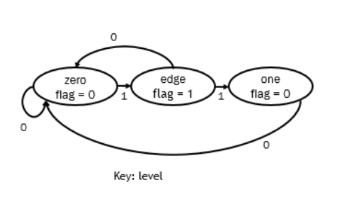
module edgeDetector
(
input wire clk, reset,
input wire level,
output reg flag
);
localparam [1:0] // define three enumerated states
zeroMoore = 2'b00,
edgeMoore = 2'b01,
oneMoore = 2'b10;
reg[1:0] stateMoore_reg, stateMoore_next;
always @(posedge clk, posedge reset)
begin
   if(reset) // if reset is high then set the state of the FSM to zero
   begin
    stateMoore_reg <= zeroMoore;
   end
   else // otherwise update the state
   begin
    stateMoore_reg <= stateMoore_next;
   end
end

always @(stateMoore_reg, level)
begin
  // the following line stores current state as the next state. This ensures that the next
  state is specified
  stateMoore_next = stateMoore_reg;
  flag= 1'b0; // set flag to zero
case(stateMoore_reg)
 zeroMoore: // if state is zero
  if(level) // and level is 1
    stateMoore_next = edgeMoore; // then set the state to edge
 edgeMoore:
   flag = 1'b1; // set flag to 1
   if(level) // if level is 1
     stateMoore_next = oneMoore; // then set the state to edge
   else
     stateMoore_next = zeroMoore; // else go to state zero
   end
oneMoore:
   if(~level) // if level is 0,
     stateMoore_next = zeroMoore; // then go to state zero.
 endcase
end
endmodule本博客所有文章除特别声明外,均采用 CC BY-NC-SA 4.0 许可协议。转载请注明来自 Chilh!
评论


