电信系统-2-second half
Line Codes and Spectra
Digital Data to Signal Conversion
◆ Four stages:
– Line coding
– Block coding(option)
– Scrambling(option)
– Modulating
数字信号波形的数学表达
The voltage (or current) waveforms for digital signals can be expressed as an orthogonal series with a finite number of terms N


wk是数字数据,w(t)是数字信号, 是N个正交函数,决定了数字波形的形状
在接收端接收到信号,如何恢复成数据:


矢量表示:


- The symbol rate (baud,波特) is defined as:

- The bit rate is defined as:

The lower bound for the bandwidth of the waveform representing the digital signal can be obtained:
- 表示数字信号的波形的带宽的下界(lower bound)


For other pulse shapes, the bandwidth will be larger than this lower bound
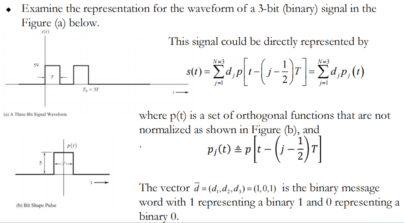
这里的p(t)没有归一化
◆ The set {pj (t)} is a set of orthogonal functions.
◆ The function p(t) is the pulse shape for each bit as show in Figure (c). p(t)是下图中的脉冲波形
◆ Using the orthogonal function approach, we can represent the waveform s(t) as exact linear combinations of 𝜑𝑗(𝑡) by 可以用𝜑𝑗(𝑡)的线性组合表示s(t)

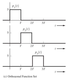

这里的𝜑𝑗(𝑡)是归一化的标准正交基
其中标准正交级数的系数为:
将这个系数在以𝜑1,𝜑2,𝜑3为基的坐标系中画出
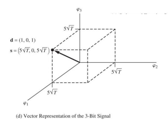
Note that for this N=3 – dimensional case with binary signalling, only 2^3=8 different waveforms could be represented (M=8). 三个基只能有八种可能的信号
Each waveform corresponds to a vector that terminates on a vertex of a cube.每一种对应一个顶点
Line coding
Line coding is the process of converting digital data to digital signals at the TX (Transmitter)
把数字信息转换成适合传输的数字脉冲信号
At the RX (Receiver), the digital data are recreated by decoding the digital signal.
通过解码数字信号重新⽣成数字数据
目的:To make the regeneration of the original signal more reliable
为什么不能采用简单的两个电平的波形(Binary Transmission)作为载波
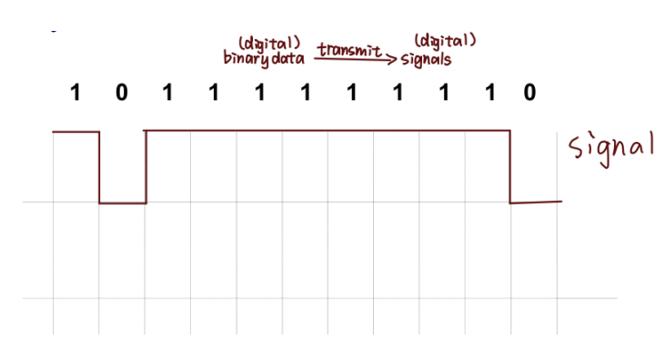
因为在传输过程中我们需要考虑两个问题:
- 随机码流中可能出现长串1或0,没有边沿存在,造成位同步信息丢失,给定时提取( timing recovery)造成困难
- 由于0和1 数量不同,直流分量会随机波动,造成基线漂移,Need zero (or constant) DC level as communications paths do not usually pass DC
- 此外因为考虑传输效率通常还需要考虑带宽
所以我们要选择不同的line code来使传输更可靠
Direct-current Component (DC)

Receivers usually use the mean value of the signal as a reference/baseline to distinguish between 1’s and 0’s
接收端通常使⽤信号的平均值 (mean value)作为参考/基线 (reference/baseline),来区分0信号和1信号

A long string of 0’s or 1’s can cause a drift in the baseline/reference
一长串的1或者0会使基准线偏离中心
DC– affects the reliability in reproducing the original signal.
Frequency just about zero and can not pass through LPF 频率几乎为0,不能通过低通滤波器
Timing and synchronisation
Timing of the incoming signal controls the reading rate.
输⼊信号的时间控制读取速率(reading rate)
It keeps the receiver synchronised with the transmitter(extracted from the pulse pattern.)
这让接收端和发射端保持同步(发送端发送一个脉冲接收方接收一个),从脉冲图中提取
A long sequences without a pulse edge makes timing very hard to maintain

没有脉冲边缘,很难计时
Line Coding Characteristics
Baseband channels do not include any frequency translation, have increasing attenuation with frequency and often block DC基带通道(baseband channels)不包括任何频率转换(frequency translation),其衰减随频率增加,经常阻塞直流(block DC)
– has a high timing content (transitions) irrespective of data to be transmitted.
– has a zero (or constant) DC level.
– must be uniquely decodable.
– must be transparent to input signal.
– must minimise the bandwidth required for transmission.
Line coding schemes

几种常用线路码
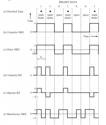
◆ Unipolar
– All signal levels are organised on one side of the time axis.

◆ Polar
– The signal voltage levels are organised on the both sides of the time axis.

◆ Bipolar
– Uses three levels: positive, zero and negative. The voltage level for one data element is at zero while other element alternates between positive and negative
必须正负交替

◆Manchester

Return-to-zero (RZ), and no return-to-zero (NRZ)
RZ:通常半个比特周期回一次0
归零码和非归零码
advantages and disadvantages
The unipolar NRZ line code has the advantage of using circuits that required only one power supply可以使用单个电源, e.g. a signal 5V power supply for the circuit,
but it has the disadvantage of requiring channels that are DC coupled因为波形有明显的直流分量,所以需要具有直流耦合能力的信道(在f=0处有很好频率响应)来传输, e.g. with frequency response down to f=0, because the waveform has a nonzero DC value.
The polar NRZ line code does not required a DC-control channel, provided that the data toggles between binary 1’s and 0’s often and that equal numbers of binary 1’s and 0’s are sent.如果0 和 1数目一样,无需具有直流耦合的信道
However, the circuitry that produces the polar NRZ signal requires a negative voltage power supply as well as a positive voltage power supply. 需要正负电压电源
The Manchester NRZ line code has the advantage of always having a 0-DC value, regardless of the data sequence, 直流分量永远为0(0 1数目必定一样)
but it has twice the bandwidth of the unipolar NRZ or polar NRZ code because the pulses are half the width. 因为脉冲宽度是unipolar和polar的二分之一,所以带宽是其两倍
其中只有unipolar一定需要直流分量
Summary of desirable properties of a line code
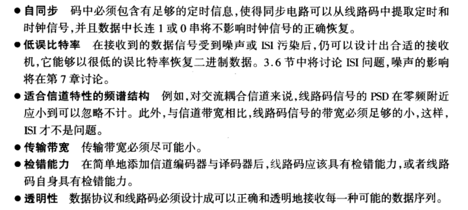
Self-synchronization.
– Three is enough timing information built into the code so that bit synchronizers can be designed to extract the timing or clock signal. A long series of binary 1’s and 0’s should not cause a problem in the time recover.
Low probability of bit error.
– Receivers can be designed that will recover the binary data with a low probability of bit error when the input data signal is corrupted by noise or ISI. The ISI problem will be discussed later.
A spectrum that is suitable for the channel
– For example, if the channel is AC coupled, the PSD of the line code signal should be negligible at frequencies near zero. In addition, the signal bandwidth needs to be sufficiently small compared to the channel bandwidth, so that ISI will not a problem.
Transmission bandwidth
– This should be as small as possible.
Error detection capability.
– it should be possible to implement this feature easily by addition of channel encoders and encoders, or the feature should be incorporated into the line code.
Transparency
– The data protocol and line code are designed so that every possible sequence of data is fathfully and transparently received.
Power spectra for binary line codes
◆ The power spectrum density (PSD) can be evaluated by using either a deterministic or a stochastic technique.
A digital signal (or line code) can be represented by
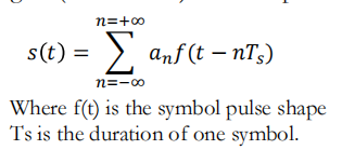
For binary signaling, 𝑇𝑠 = 𝑇𝑏, where 𝑇𝑏 is the time that it takes to send 1 bit.
For multilevel signaling, 𝑇𝑠 = 𝑙𝑇b
The set {𝑎𝑛} is the set of random data. For example, for the unipolar NRZ line code  and 𝑎𝑛 = +𝐴 V when a binary 1 is sent, and 𝑎𝑛 = 0 V when a binary 0 is sent
The general expression for the PSD of a digital signal can be expressed by
$$
P(f)=\frac{|F(f)|^2}{T_s} \sum_{k=-\infty}^{\infty} R(k) e^{j 2 \pi k f T_S}
$$
F(f) is the Fourier transform of the pulse shape(波形) f(t)
R(k) is the autocorrelation(自相关系数) of the data
$$
\mathrm{R}(k)=\sum_{i=1}^l\left(a_n a_{n+k}\right)_i P_i
$$
Note that equation shows that the spectrum of the digital signal depends on two things:
– The pulse shape used
– Statistical properties of the data
Unipolar NRZ signalling
For unipolar signalling, the possible levels for the a’s are +A and 0 V
Assume that these values are equally likely to occur and that data are independent

计算R(k):
k=0时 the possible products of 𝑎𝑛 × 𝑎𝑛 are 𝐴 × 𝐴 = 𝐴 2 and 0 × 0 = 0, and consequently, 𝐼 = 2 (an×an 可能值只有这两种)For random data, the probability of having
 is 50%, and the probability of having 0 is 50%
For 𝑘 ≠ 0, there are I=4 possibilities for the product values: 𝐴 × 𝐴, 𝐴 ×0, 𝑎𝑛𝑑 0 × 𝐴, 0 × 0. They all occur with a probability of ¼

- Overall
$$
\mathrm{R}_{\text {unipolar }}(k)=\left{\begin{array}{ll}
\frac{1}{2} A^2 & k=0 \
\frac{1}{4} A^2 & k \neq 0
\end{array}\right}
$$
求PSD
For rectangular NRZ pulse shape, the Fourier transform pair is

使用上面PSD的公式:𝑇𝑠 = 𝑇𝑏, we find that the PSD for the unipolar NRZ line code is

with a weight of ½.
有泊松和公式:

最后可得:
$$
P_{\text {unipolar } N R Z}(f)=\frac{A^2 T_b}{4}\left(\frac{\sin \pi f T_b}{\pi f T_b}\right)^2\left[1+\frac{1}{T_b} \sum_{n=-\infty}^{\infty} \delta\left(f-\frac{n}{T_b}\right)\right]
$$

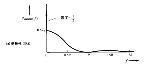
If A is selected so that the normalized average power of the unipolar NRZ signal is unity取单极性NRZ信号的归一化平均功率为单位值, then
The PSD is plotted in Figure (a), where , the bit rate of the line code横坐标是线路码的比特率
由于$ \lim\limits_{f \to 0}{P(f)=\frac{1}{2T_b}+\frac{1}{2}\delta(f)} $可以看到坐标轴0点处,存在冲激

Polar NRZ signalling
For polar NRZ signaling, the possible levels for a’s are +A and –A V. For equally likely occurrences of +A and –A, and assuming that the data are independent of bit to bit, we get
假设信号中这两种水平电荷出现概率相同,且数据位与位之间独立

自相关系数

For 𝑘 ≠ 0

Thus 
代入傅里叶变换对以及PSD公式:
功率
$$
P_{\text {polar } N R Z}(f)=A^2 T_b\left(\frac{\sin \pi f T_b}{\pi f T_b}\right)^2
$$

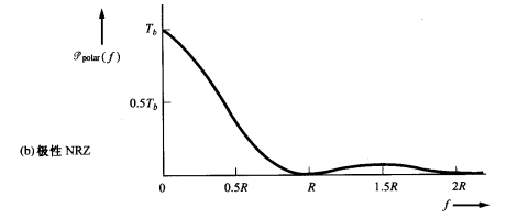
The polar signal has the disadvantage of having a large PSD near DC
The probability of bit error performance(误比特率性能) is superior to that of other signaling methods.
0点纵轴坐标:$ \lim\limits_{f \to 0}{P(f)=T_b} $
Unipolar RZ signalling
自相关系数已经在前面给出(与NRZ相同)

For RZ signaling, the pulse duration is 𝑇𝑏/2 instead of 𝑇𝑏, as used in NRZ signaling. That is, for RZ(对应RZ来说,脉冲周期为 𝑇𝑏/2,Ts=Tb/2)

代入傅里叶变换对以及PSD公式:
$$
P_{\text {unipolar } R Z}(f)=\frac{A^2 T_b}{16}\left(\frac{\sin \pi f T_b / 2}{\pi f T_b / 2}\right)^2\left[1+\frac{1}{T_b} \sum_{n=-\infty}^{\infty} \delta\left(f-\frac{n}{T_b}\right)\right]
$$
$$
\lim\limits_{f \to 0}{P(f)=\frac{1}{4T_b}+\frac{1}{4}\delta(f)}
$$
f=R时
$$
{P(R)=\frac{1}{\pi^2 T_b}+\frac{1}{\pi^2}\delta(f-R)}
$$

Bipolar RZ signalling

The permitted values for 𝑎𝑛 are +A, -A, and 0 where binary 1’s are represented by alternation +A and –A values, a binary 0 is represented by 𝑎𝑛 = 0.

For 𝑘 = 1 (只考虑相邻比特的电平) and the data sequences 数据序列为(1,1), (1,0), (0,1) and (0,0) 𝑎𝑛 与𝑎𝑛+1乘积可能值为 , 0, 0 and 0,每个的概率为0.25

For 𝑘 > 1, the bits being considered are not adjacent and an和an+k乘积为 , 0, 0 and 0
且$A^2 和-A^2$可能发生概率为0.125
$$
\mathrm{R}(k>1)=\sum_{i=1}^8\left(a_n a_{n+k}\right)_i P_i=A^2 \frac{1}{8}-A^2 \frac{1}{8}=0
$$
Overall autocorrelation
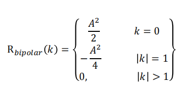
𝑇𝑠 = 𝑇𝑏/2, we find that the PSD for the bipolar RZ line code is

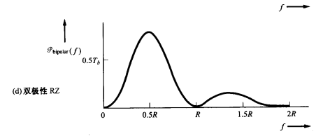

Manchester NRZ signalling
The PSD for Manchester


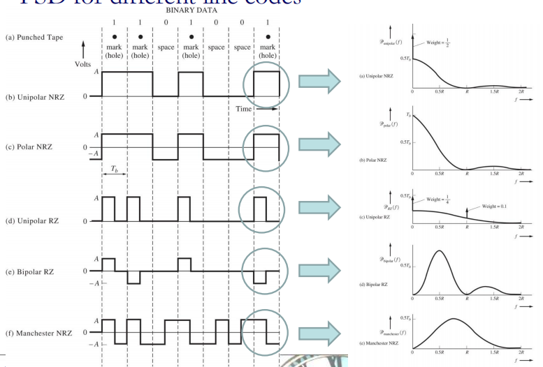
| unipolar NRZ | 有DC分量 | R=0 有1/2冲击脉冲 | 带宽为R |
|---|---|---|---|
| polar NRZ | 有DC分量 | 无脉冲 | 带宽为R |
| unipolar RZ | 有DC分量 | R=0 R=R有脉冲 | 带宽为2R |
| bipolar RZ | 无DC分量 | 无脉冲 | 带宽为R |
| Manchester NRZ | 无DC分量 | 无脉冲 | 带宽为2R |
Power spectra for multilevel polar NRZ signal
Multilevel signalling provides reduced bandwidth compared with binary signalling
𝑙 = 3-bit DAC is used, so that 𝐿 = 2^3 = 8 levels
其NRZ的图像(区分Tb和Ts)

与之对应的w与t的图像 shows the corresponding eight-level multilevel output waveform,
where Ts is the time it takes to send on multilevel symbol
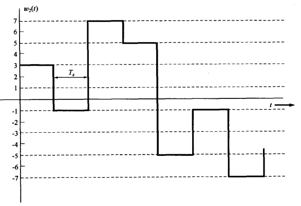

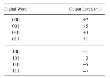
当上表中各值等概率出现时,计算R(k):
k=0时
𝑘 ≠ 0时, 𝑅 (𝑘) = 0
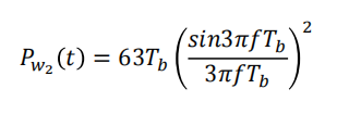
可以得w2(t)的PSD为

Where the pulse width (or symbol width) is $$T_s=3T_b$$
For the rectangular pulse shape of width $3𝑇_𝑏$, this becomes
Spectral efficiency

The maximum possible spectral efficiency is limed by the channel noise if the error is to be small. It can be given by Shannon’s channel capacity formula

The spectral efficiency for multilevel polar NRZ signalling is obtained by
substituting  (0点带宽)to equation, so that

多进制polar NRZ
各种line code的spectral efficiency

Inter-symbol Interference (ISI)
码间串扰:
- 整个系统 (发送机 、接收机和信道 )中有各种类型的滤波器 (以及惰性 电路元件 ,如电感和电容 )
– Filters and linear amplifiers in transmitter propagation medium
– Filters and linear amplifiers in the front end of the receiver
– Filters used in the demodulation process
- Electrical noise and interference produced by a variety of sources
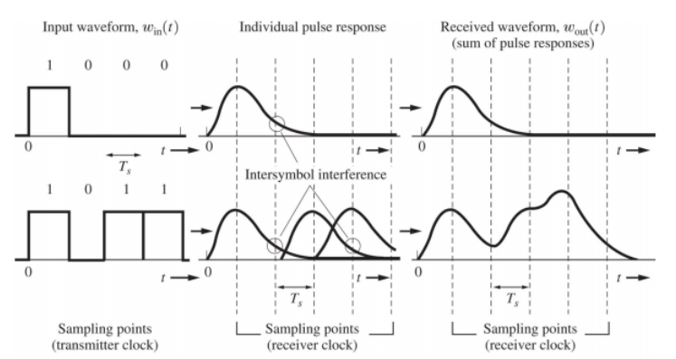
这两个原因会造成信号的码间串扰,什么是码间串扰:
由千系统的滤波作用 ,接收脉冲之间会发生交迭。脉冲出现拖尾占据了相邻码元间隔 ,从而干扰了信号检测过程 ,进而造成误差性能的降低。即便没有噪声,滤波和信道引起的失真也会导致码间串扰。
为了补偿发射机和信道引起的失真 ,接收滤波器通常是均衡滤波器 (equalizing filter):
该滤波器可以等效成一个系统其传输函数为:


传输过程中,如果没有控制好速率,那么在接受下一个符号前,上一个符号还在传输,产生了重叠,这样就造成了ISI
Eye diagram
分析工具
Use eye diagram to make an engineering judgement on the likely performance and source of degradation in a data communications link
通过眼图来反映码间串扰和噪声对系统性能的影响:“眼睛“张开的宽度表示可采样的时间范围 ,显然 ,最佳采样时刻应是 “眼睛“张开最大的时刻 ,此时受噪声干扰最小(码间串扰最小) 。
眼图的最常见用途是定性地估计码间串扰 的程度 。当 “眼睛"闭合时 ,码间串扰增加 ;“眼睛"睁开时 ,码间串扰减少 。
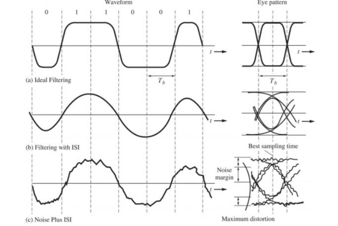
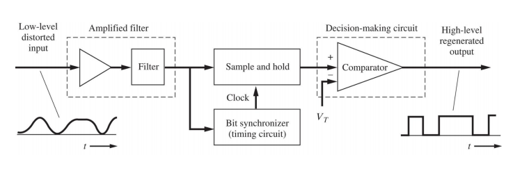
图a:理想滤波器,没有噪声,filter的带宽合适,没有ISI,所以眼图张的很大,且十分端正
图b:filter的带宽不合适产生了ISI,没有噪声,所以眼图没有完全张开,且不端正
图c:filter的带宽不合适产生了ISI,且有噪声干扰,所以眼图张的更小,更不端正,且模糊不清
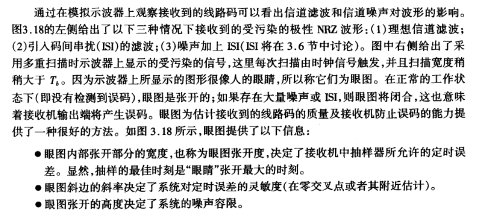
Regenerative repeater for unipolar NRZ signalling

Synchronisation Signals
用来同步信号:类似时钟
◆ Synchronisation signals are clock-type signals that are necessary within a receiver (or repeater) for detection (or regeneration) of the data from the corrupted input signal.

◆ 数字通信通常至少需要三种类型的同步信号:
–位同步,用于区分一个bit间隔和另一个bit间隔;
–帧同步,用于区分一组数据;
–载波同步,用于带通信号的相干检波。
Systems are designed so that the sync is derived either directly from the corrupted signal or from a separate channel that is used only to transmit the sync information.
系统的设计使同步要么直接从损坏的信号中获得,要么从仅用于传输同步信息的单独通道中获得。
减小ISI
◆ ISI can be reduced by increasing the channel bandwidth.
◆ Reshape the pulse from the transmitter to minimise the ISI
Baseband pulse-transmission system
Consider a digital signalling system as shown in Figure below, in which the flat-topped (矩形波)multilevel signal at the input is
where , and 𝑎𝑛(系数) may take on any of the allowed L multilevel (L=2 for binary signalling). The symbol rate is 𝐷 = 1/𝑇𝑠 pulses/s.
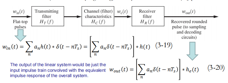
输出信号是输入信号于系统冲激响应的卷积:其中等效冲激响应为

h(t)是矩形波
he(t)也具有脉冲形状,当单个平顶脉冲激励发送滤波器时,接收滤波器输出就是he(t)波形


矩形波的傅里叶变换

◆ When $𝐻_𝑒(𝑓)$ is chosen to minimize the ISI, $𝐻_𝑅(𝑓) $, obtained from equation (3-64) is called an equalising filter. 当选择的$𝐻_𝑒(𝑓)$使ISI最小,称上式中$𝐻_𝑅(𝑓) $为均衡滤波器

The output of the receiving filter is

The output pulse shape is affected by
– the input pulse shape (flat-topped in this case)
– The transmitter filter
– The channel filter
– The receiving filter


Nyquist’s First Method (Zero ISI)


Then, there will be no ISI
但是想让冲激响应成为sinc函数在工程上存在两个问题:
所以必须退而求其次找一个好实现,且ISI小的函数:
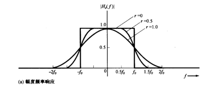
Raised cosine-rolloff Nyquist filtering
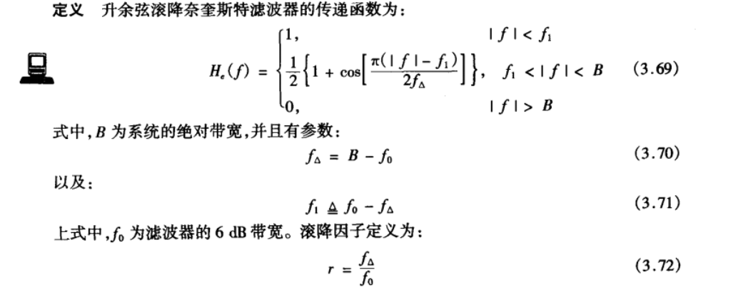


Plots of the frequency response and impulse response for rollofffactors r=0, r=0.5 and r=1.
频域:
时域:
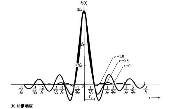
The baud rate of the raised cosine rolloff system with ISI free is

满足奈奎斯特第一准则系统所能支持的最大波特率
Time-Division Multiplexing

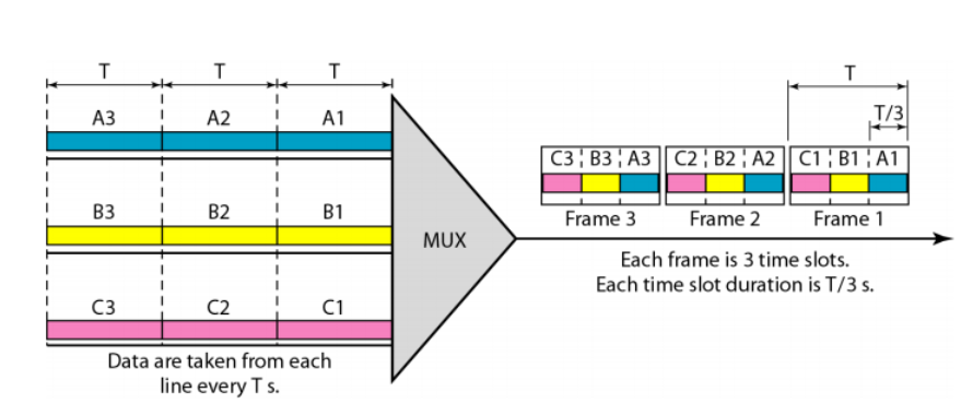
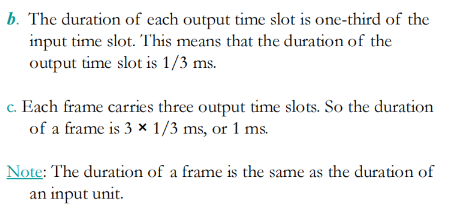
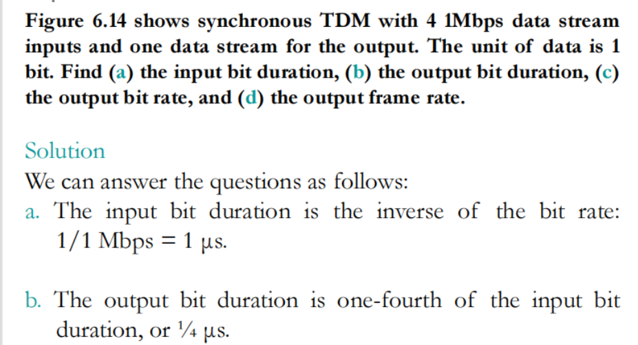
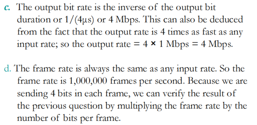
TDM is a digital multiplexing technique for combining several low-rate digital channels into one high-rate one.
In synchronous TDM, the data rate of the link is n times faster, and the unit duration is n times shorter.
由于帧是提前分配的所以长度是固定的(帧的长度无论是否TDM都固定),但是帧内的片数必须和通道数保持一致,所以data rate快n倍
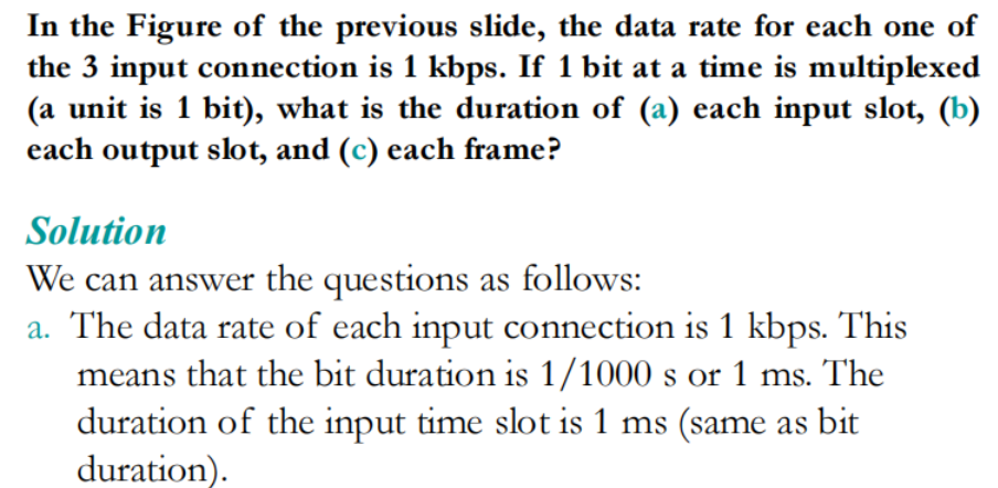
题目

Modulation Techniques
调制与编码是用来把模拟(数字)信息转化为数字(模拟)信号的过程
数据:某种要传输的信息
信号:数据的电气或电磁表现
用数字信号承载数字或模拟数据——编码
用模拟信号承载数字或模拟数据——调制
四种转换:
Digital data, digital signal:设备比数模调制设备更简单、更便宜
Analog data, digital signal:允许使用现代数字传输和交换设备(PAM、DM)
Digital data, analog signal:有些传输介质只传播模拟信号
Analog data, analog signal:电子形式的模拟数据可以方便而廉价地传输,通过语音级线路进行语音传输
信噪比、数据率、带宽决定了接收器成功接收信号的程度
◆ An increase in data rate increases bit error rate
◆ An increase in SNR decreases bit error rate
◆ An increase in bandwidth allows an increase in data rate
数字数据转模拟信号
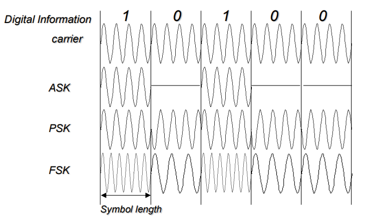
– Amplitude-shift keying (ASK)
• Amplitude difference of carrier frequency
– Frequency-shift keying (FSK)
• Frequency difference near carrier frequency
– Phase-shift keying (PSK)
• Phase of carrier signal shifted

分别对载波的振幅、频率和相位进行操作,使其可以表示各种数据
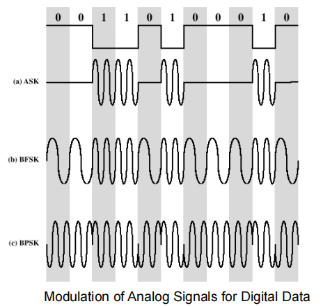
都是以三角函数为载波
Amplitude-Shift Keying
幅移键控
通过移动幅度表示数据
◆ One binary digit represented by presence of carrier, at constant amplitude
◆ Other binary digit represented by absence of carrier

Binary Frequency-Shift Keying
通过移动频率表示数据
Two binary digits represented by two different frequencies near the carrier frequency

Multiple Frequency-Shift Keying (MFSK)
◆ More than two frequencies are used
◆ More bandwidth efficient but more susceptible to error


To match data rate of input bit stream, each output signal element is held for:
Ts =LT seconds
where T is the bit period (data rate = 1/T)


用四种不同的频率表示来表示一种数据(data)
Phase-Shift Keying (PSK)

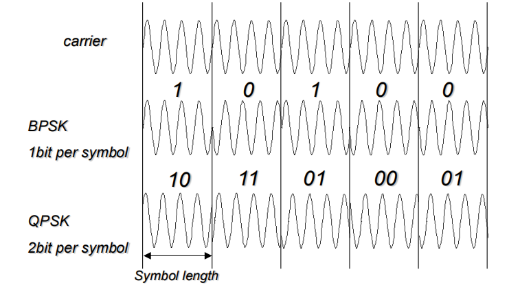
◆ Two-level PSK (BPSK):Uses two phases to represent binary digits

◆ Four-level PSK (QPSK)
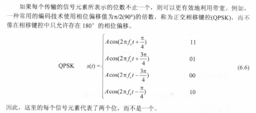
每个之间差90°
Multi bit modulation
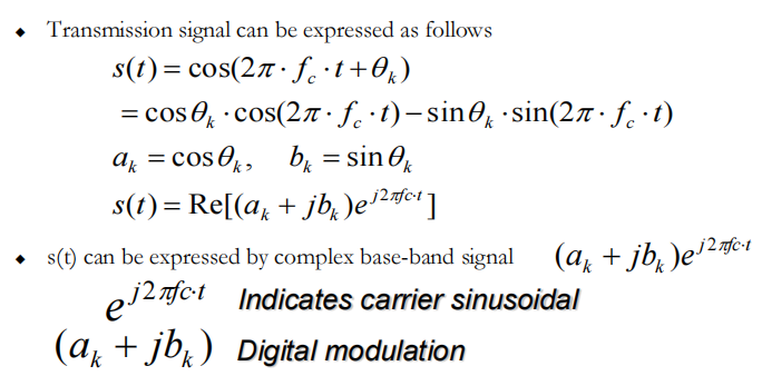
数字调制的数学表示
用复数形式表示三角函数载波
Constellation map(星座图)
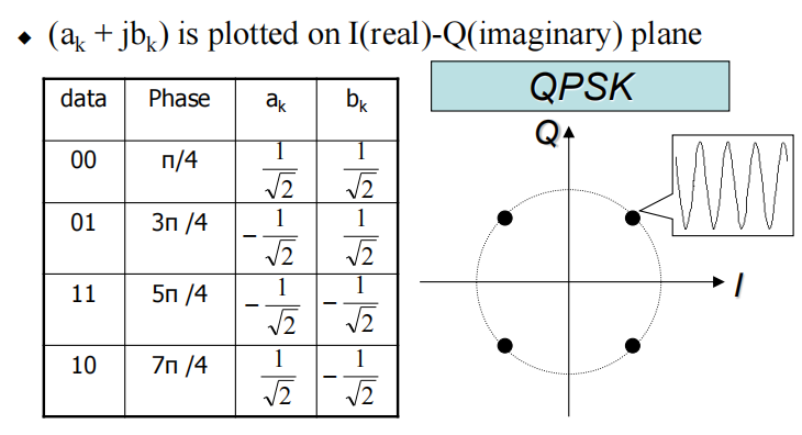
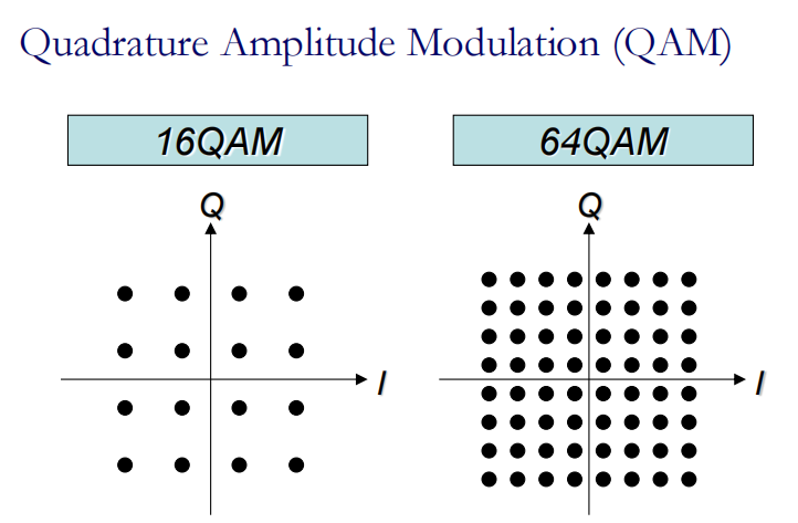
可以理解成幅度加相位调制:QAM也被认为相位调制和幅度调制的组合。
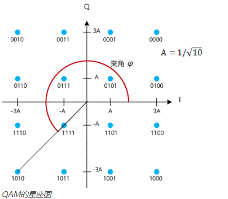
◆ Type of modulation: ASK,PSK,FSK,QAM
◆ OFDM uses PSK and QAM
◆ Digital modulation is mathematically characterized by the coefficient of complex base-band signal

Spread Spectrum
扩频:采用前面学的调制技术可以让信号在不同频率进行传递,如M=4的MFSK中把信道分成频率不同的四个部分进行传递,但是这四个频率集中于中心频率且有一个较窄的带宽。扩频技术就是再对这个信道进行扩展,如可以扩展到4个信道(每四个一组)并且随机编码,使得信息传输时,在不同信道(四个)上随机跳转。这样 种跳转规律只有输入输出可以同步。对于窃听者无法得知,所以看起来像是一串乱码
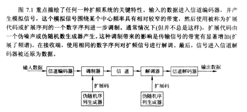
Effect of modulation is to increase bandwidth of signal to be transmitted
General Model of Spread Spectrum Digital Communication System:
两种扩频技术
Frequency Hoping Spread Spectrum (FHSS)
Direct Sequence Spread Spectrum (DSSS)
Frequency Hoping Spread Spectrum (FHSS)
调频扩频
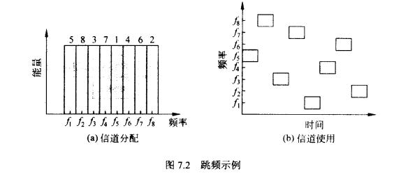
◆ Signal is broadcast over seemingly random series of radio frequencies
◆ Signal hops from frequency to frequency at fixed intervals
信号在固定间隔里从一个频率跳到另一个频率。接收器知道这个跳转规则,也会跳频接收
这个载波经过一个时间间隔它的频率会突然变到另一个频率然后继续传输在外界看来,这个频率隔一会就变一下,难以解读但是发送方和接收方都知道这个信号频率的跳动方式所以可以抗干扰
Receiver, hopping between frequencies in synchronization with transmitter, picks up message
Channel sequence dictated by spreading code(PN码 扩频码(噪声、伪随机数)决定传输的信道)
- Advantages
– Eavesdroppers hear only unintelligible blips(偷听者只听到难以理解的信号)
– Attempts to jam signal on one frequency succeed only at knocking out a few bits(在一个频率上干扰信号的尝试只能成功地破坏几个比特)
FHSS Using MFSK 使用多相频移键控的跳频
MFSK signal is translated to a new frequency every Tc seconds by modulating the MFSK signal with the FHSS carrier signal
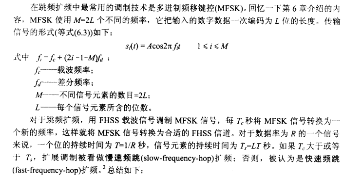
写的有点问题: $M=2^L$
◆ For data rate of R:
– duration of a bit: T = 1/R seconds
– duration of signal symbol: Ts = LT seconds
Tc是转换信道的周期
◆ Tc >= Ts – slow-frequency-hop spread spectrum 慢速频跳扩频
◆ Tc < Ts - fast-frequency-hop spread spectrum 快速频跳扩频
Slow FHSS Using MFSK (M = 4,k= 2)
M个不同的频率,K是PN码(随机扩频码)使用的比特
也就是说MFSK中把一个信道分成四个不同频率的部分
又被扩展了四倍
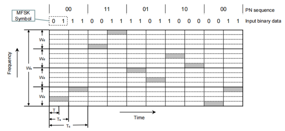
可以看到PN=00时采用最低频率的带宽传输信号,PN=11采用最高频率
MFSK的带宽是Wd
FHSS的带宽是Ws
快速FHSS:Fast FHSS Using MFSK (M = 4, k = 2)
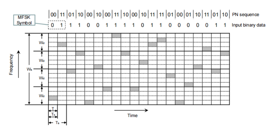
每个symbol传输都需要两种频率
FHSS Performance Considerations
◆ Large number of frequencies used
◆ Results in a system that is quite resistant to jamming
– Jammer must jam all frequencies
– With fixed power, this reduces the jamming power in any one frequency band
在固定功率的情况下,这减少了任何一个频段的干扰功率
Direct Sequence Spread Spectrum (DSSS)
◆ Each bit in original signal is represented by multiple bits in the transmitted signal
原来一位表示的数据,现在用多个位表示。
Spreading code spreads signal across a wider frequency band
One technique combines digital information stream with the spreading code bit stream using exclusive-OR
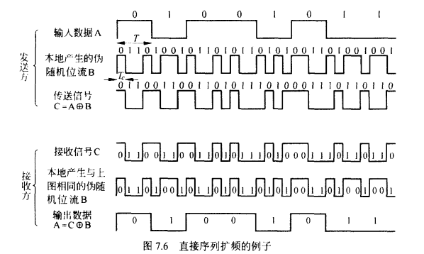
利用异或将数字信息与扩展编码位流结合。
可以看到这里脉冲信号宽度(周期)缩短4倍,所以频率扩大了四倍(前面讲RZ linecode也有类似的)
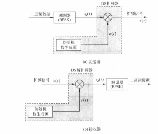
DSSS Using BPSK 使用二相相移键控的直接序列扩频
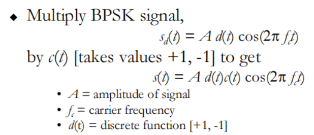
C(t)是[-1,1]内的随机PN序列

在接收端, incoming signal multiplied by c(t)
– Since, c(t) x c(t) = 1, incoming signal is recovered
收到的信号乘c(t),恢复原信号
Code-Division Multiple Access
码分多址: 有很多数据通过前面的调制以及扩频技术发送传输(在一个信道),CDMA就是保证每个用户发送信号在乘以一个不同的c(t)的条件下,传输到接收方,接收方可以正确区分想要的信号,不会被别的用户的信号所干扰(与时分复用一个功能)。
Basic Principles of CDMA
– D = rate of data signal
– Break each bit into k chips
• Chips are a user-specific fixed pattern (每个用户的编码模式不一样)
– Chip data rate of new channel = kD(保证与之前数据率一样,现在每秒需要发KD个分片)
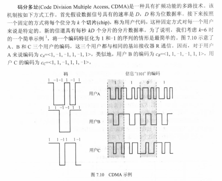
If k=6 and code is a sequence of 1s and -1s
For a ‘1’ bit, A sends code as chip pattern <c1, c2, c3, c4, c5, c6>
For a ‘0’ bit, A sends complement of code <-c1, -c2, -c3, -c4, -c5, -c6>(相反)
received chip pattern(接收到的分片图样):*<*d1, d2, d3, d4, d5, d6>
解码:
u代表用户,[-6,6]
- 以A为例子:User A code = <1, –1, –1, 1, –1, 1>
– To send a 1 bit = <1, –1, –1, 1, –1, 1>
– To send a 0 bit = <–1, 1, 1, –1, 1, –1>
- 以B为例子:User B code = <1, 1, –1, – 1, 1, 1>
– To send a 1 bit = <1, 1, –1, –1, 1, 1>
Receiver receiving with A’s code

• User A ‘1’ bit: 6 -> 1
• User A ‘0’ bit: -6 -> 0
• User B ‘1’ bit: 0 -> unwanted signal ignored(出错了或者是别的用户的数据)
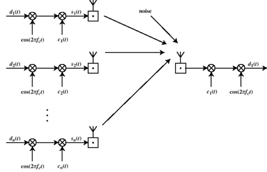
n个用户分别用BPSK调制后用DSSS扩频,由于扩频码不一样(相互正交)接收信号可以唯一收到目的信号
Categories of Spreading Sequences
扩展序列分类
Spreading Sequence Categories
– PN sequences(伪随机数)
– Orthogonal codes(正交编码)

◆ For FHSS systems
– PN sequences most common
◆ For DSSS systems not employing CDMA
– PN sequences most common
◆ For DSSS CDMA systems
– PN sequences
– Orthogonal codes
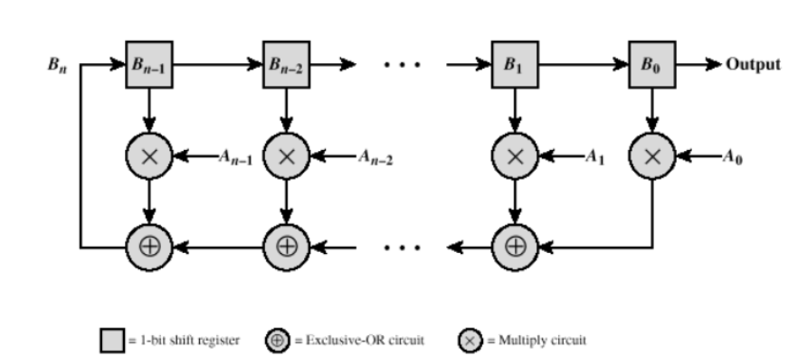
PN Sequences 伪随机数序列
◆ PN (Pseudonoise) generator produces periodic sequence that appears to be random
◆ PN Sequences
– Generated by an algorithm using initial seed
– Sequence isn’t statistically random but will pass many test of randomness
– Sequences referred to as pseudorandom numbers or pseudonoise sequences
– Unless algorithm and seed are known, the sequence is impractical to predict

Important PN Properties
◆ Randomness– Uniform distribution
• Balance property
• Run property
– Independence
– Correlation property
◆ Unpredictability
通过Linear Feedback Shift Register Implementation实现:
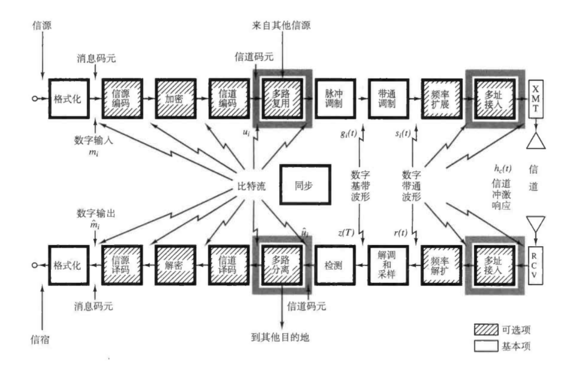
Multiple Access Techniques
Multiplexing:复用,更多的关注于对同一资源(如时空频码)的分配。(前面讲了时分复用)
multiple access:多址,更多的体现在对共同工作在同一资源上的多个用户的区分上面。
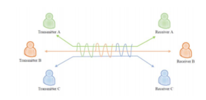
Multiple access
Multiple Access: to enable multiple users to share the same channel simultaneously.
◆ Possible approaches for multiple access
– Time.时分
– Pitch.频分
– Language.码分

Frequency Division Multiple Access (FDMA)
◆ Key features:
– Assign each user to a particular channel.
– Transmit signals simultaneously and continuously. to enable multiple users to share the same channel simultaneously
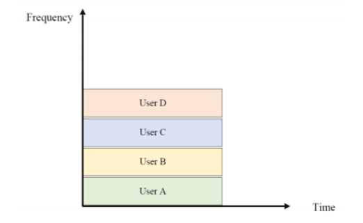
◆ Application: all 1G systems use FDMA
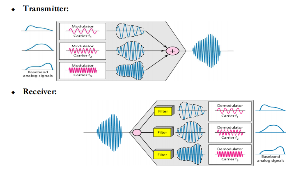
◆ Advantages
– Low overhead
– Simple hardware at users and base stations
◆ Disadvantages
– If no talking, a channel sits idle (resource waste)
– Require tight radio frequency filters
Time Division Multiple Access (TDMA)
◆ Key features
– Single carrier frequency with multiple users.
– Non-continuous transmission.
– Each user occupies a cyclically repeating time slot.
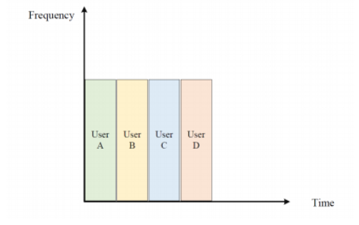
◆ Application: most 2G systems use TDMA
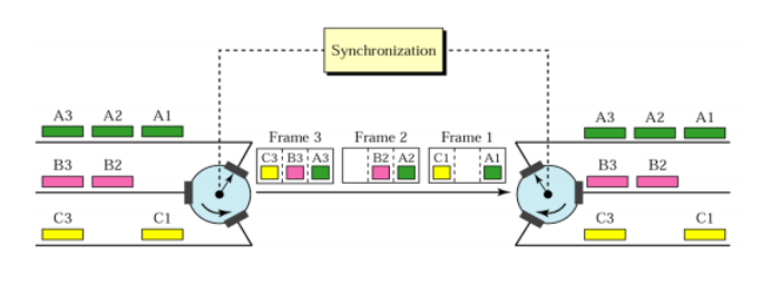
◆ Advantages
– Interference-free technique.
– Low battery consumption.
– Slots can be assigned on demand.
◆ Disadvantages:
– “CLOCK” is required.
– Large synchronization overheads.
GSM(全球移动通信系统)Multiple access
uses combined TDMA/FDMA
Code Division Multiple Access (CDMA)
◆ Key features
– All users use same time and frequency.
– Narrowband signals multiplied by wideband spreading codes.
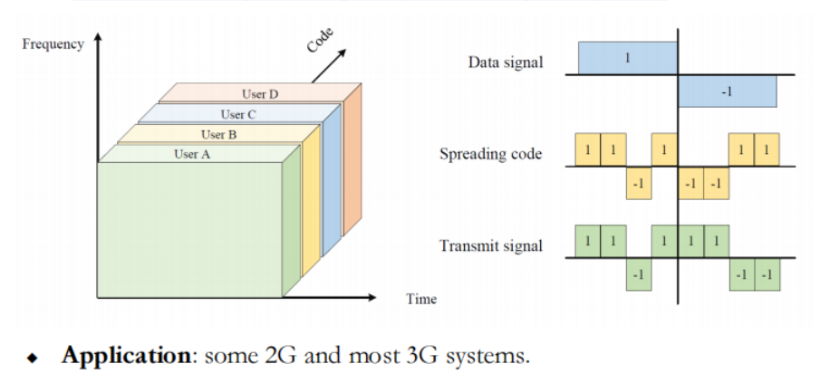
◆ Advantages
– Easy addition of more users.
– No absolute limit on the number of users.
◆ Disadvantages
– QoS decreases as the number of users increases.
– Near-far problem exists (power control is required).
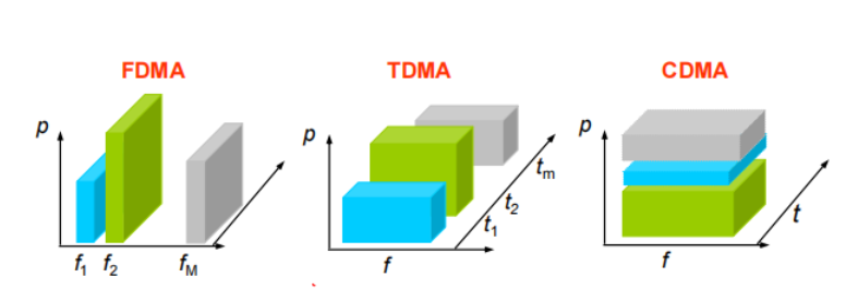
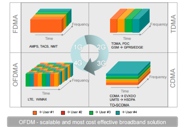
◆FDMA:不同的频段分配给不同的用户。
◆TDMA:不同的时间段分配给不同的用户。
◆CDMA:不同的用户分配不同的编码。
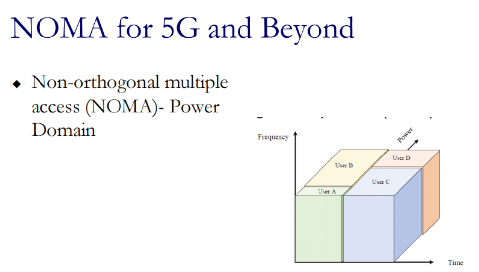
OFDMA for 4G (3GPP LTE/LTE-A)

◆ Many orthogonal sub-carriers are multiplexed in one symbol

◆ OFDMA is a multi-user version of the popular OFDM digital modulation scheme. Multiple access is achieved in OFDMA by assigning subsets of subcarriers to individual users
普通FDMA 的频谱:
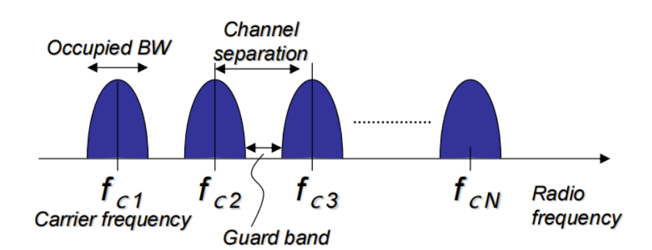
为了防止ISI,保证各个频谱间有Guard Band
Use multiple channel (carrier frequency) for one data transmission
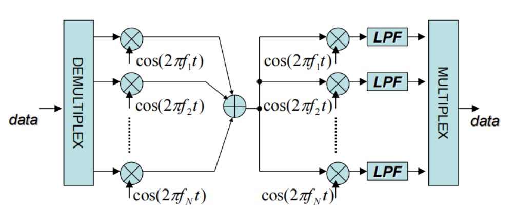
在sender乘不同的载波,再在接收端接收后乘不同的载波信号(正交特性使不想关的都为0)
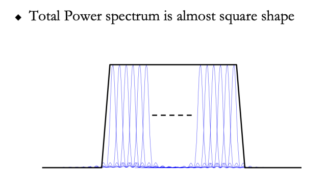
如果使用OFDM,各个载波是正交的所以不用有 guard band 甚至可以重叠提高带宽利用率
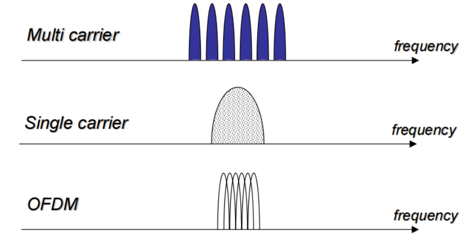
◆ OFDM is a multi-carrier modulation
◆ OFDM sub-carrier spectrum is overlapping
◆ In FDMA, band-pass filter separates each transmission(带通滤波器可以将其分开)
In OFDM, each sub-carrier is separated by DFT because carriers are orthogonal
◆ Each sub-carrier is modulated by PSK, QAM
OFDM carriers
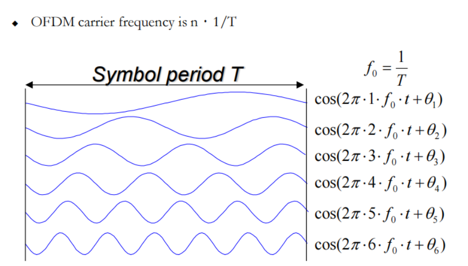
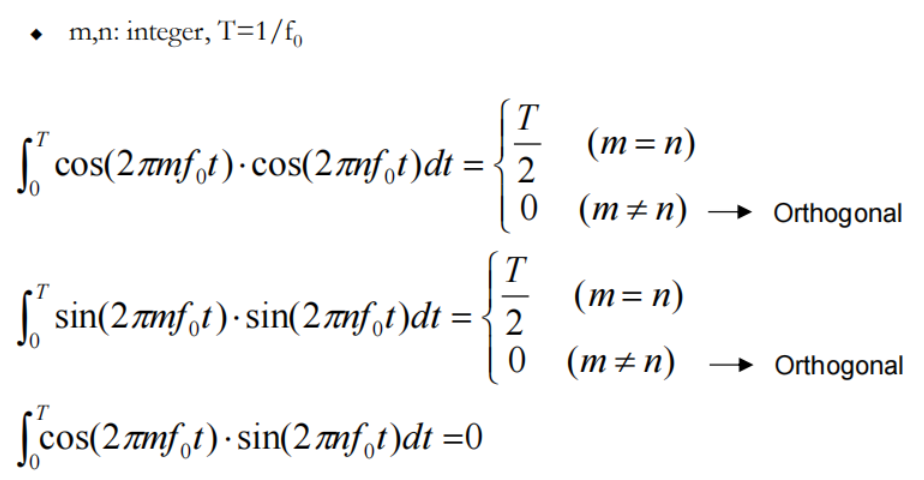
都是正交的(信号与系统)
相位和幅度共同表示了要传递的信息:

所以说:Amplitude and Phase will be digitally modulated
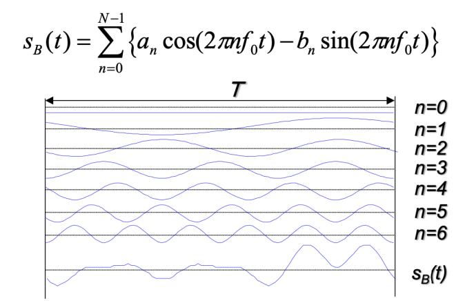
在时域上将各个信号叠加起来就得到了Sb(t)
在接收端可以根据正交性解调(乘上想要的那个信息对应的载波,可以获得想要的信息)
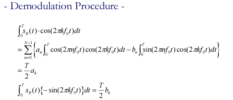
According to the sinusoidal orthogonality, an ,bn can be extracted
实际工程实现使用DFT(FFT)
OFDM频谱
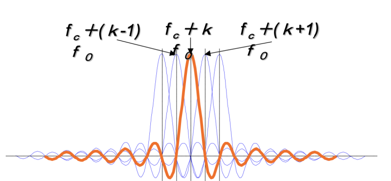
fc+(k-1)f0
OFDM signal generation

直接生成需要
N digital modulators
N carrier frequency generator
不太现实,所以要使用DFT的方法
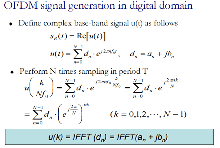
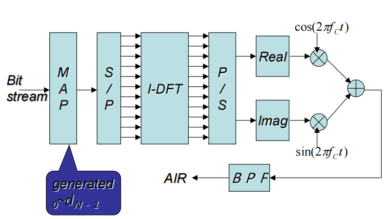
MAP形成dn-> S/P串转并->IDFT得到了这个u(k),是一堆复指数的和,携带着信息
->并转串->实部虚部分别乘载波->带通滤波器->传播到空气中
OFDM demodulation
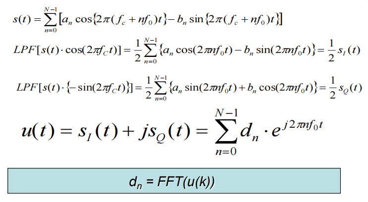
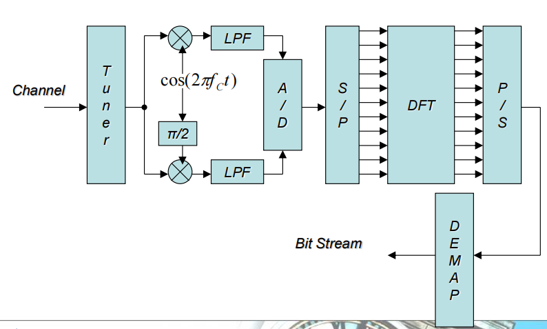
◆ Each symbol carries information
◆ Each symbol wave is sum of many sinusoidal
◆ Each sinusoidal wave can be PSK, QAM modulated
◆ Using IDFT and DFT, OFDM implementation became practica
Multi-path

相同信号可能通过不同的路径传播,由于路不同,有延时存在,接收方会造成ISI
多径效应(multipath effect):指电磁波经不同路径传播后,各分量场到达接收端时间不同,按各自相位相互叠加而造成干扰,使得原来的信号失真,或者产生错误
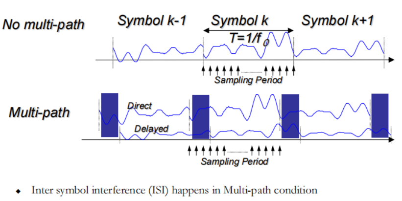
图中不同符号间产生干扰(由于到达时间不同)
Cyclic Prefix (Guard Interval) Tg
为了避免符号间干扰,可以在OFDM符号之间以循环前缀的形式插入保护周期。该保护周期是前一个符号的时延扩展分量在下一个符号开始之前到达提供了一个时间窗口。
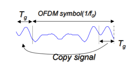
在实际系统中使用OFDM符号的周期扩展作为循环嵌缀,将OFDM符号的最后一段的时域信号的拷贝插入到保护时间当中。
By adding Cyclic Prefix, orthogonality can be maintained
multi-path causes Amplitude and Phase distortion for each sub-carrier造成各个载波的相位(旋转)幅度(到原点距离变了)畸变
失真必须由均衡器补偿
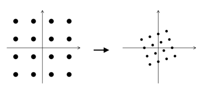
OFDM 总结
High Frequency utilization by the square spectrum shape
Multi-path problem is solved by Cyclic Prefix
Multiple services in one OFDM by sharing sub-carriers
Implementation was complicated but NOW possible because of LSI technology progress
Radio Propagations、Network Architecture
Radio Propagations
无线电传输
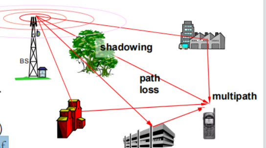
Radio transmission impairments
◆ Path loss
接收功率随距离增加而减小。
◆ Shadowing ( slow fading )
因建筑物、山峦、树木及树叶阻塞而造成。
◆ Multipath fading ( fast fading )
由物体对透射波的多径反射引起
Introduction
◆ An antenna is an electrical conductor or system of conductors
– Transmission - radiates electromagnetic energy into space
– Reception - collects electromagnetic energy from space
◆ In two-way communication, the same antenna can be used for transmission and reception

Radiation pattern(辐射图样)
-天线辐射特性的图形表示
-用二维截面表示

Beam width (or half-power beam width)
– Measure of directivity of antenna

Reception pattern(接收图样)
– Receiving antenna’s equivalent to radiation pattern接收方的辐射图样
Antenna Gain(无线增益)
Power output, in a particular direction, compared to that produced in any direction by a perfect omnidirectional antenna (isotropic antenna)

Effective area
– Related to physical size and shape of antenna


Propagation Modes(传播方式)


Line of Sight (LOS) Wireless Transmission Impairments
◆ Attenuation and distortion
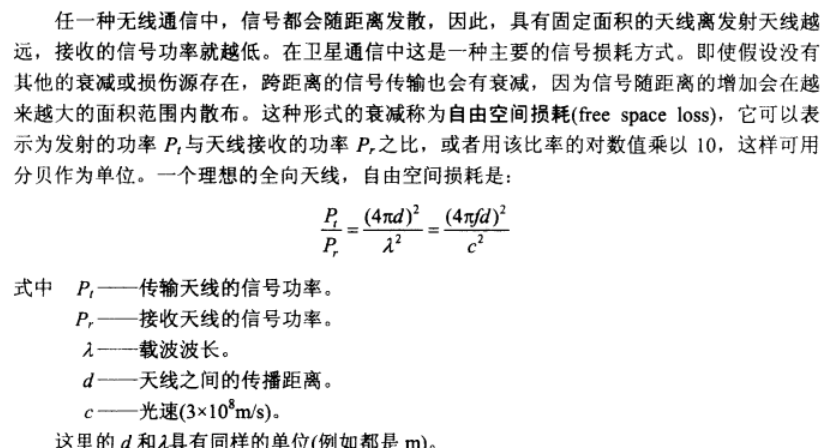
◆ Free space loss
◆ Noise
◆ Atmospheric absorption
◆ Multipath
◆ Refraction
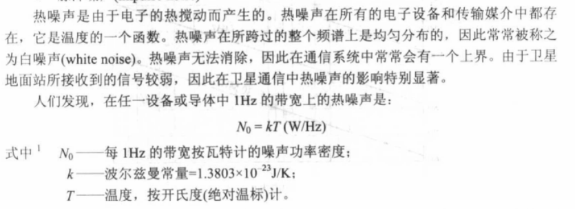
◆ Thermal noise

Attenuation
◆ Strength of signal falls off with distance over transmission medium
◆ Attenuation factors for unguided media:
– Received signal must have sufficient strength so that circuitry in the receiver can interpret the signal
– Signal must maintain a level sufficiently higher than noise to be received without error
– Attenuation is greater at higher frequencies, causing distortion


Free Space Loss 自由空间损耗

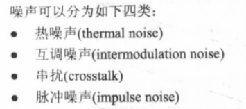
Categories of Noise
Thermal Noise 热噪声


Noise Terminology
◆ Intermodulation noise – occurs if signals with different frequencies share the same medium
– Interference caused by a signal produced at a frequency that is the sum or difference of original frequencies
◆ Crosstalk – unwanted coupling between signal paths
◆ Impulse noise – irregular pulses or noise spikes
– Short duration and of relatively high amplitude
– Caused by external electromagnetic disturbances, or faults and flaws in the communications system
Expression Eb/N0
◆ Ratio of signal energy per bit to noise power density per Hertz每比特信号能量与每赫兹噪声功率密度的比值


N0=kT 是上面的1Hz的热噪声
The bit error rate for digital data is a function of Eb/N0
– Given a value for Eb/N0 to achieve a desired error rate, parameters of this formula can be selected
– As bit rate R increases, transmitted signal power must increase to maintain required Eb/N0

Other Impairments
◆ Atmospheric absorption – water vapor and oxygen contribute to attenuation
大气吸收:主要由水蒸气、氧气造成
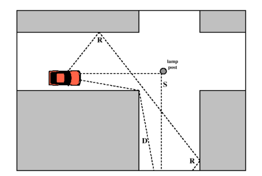
◆ Multipath – obstacles reflect signals so that multiple copies with varying delays are received
多径:障碍物反射信号,因此可以接收多个延迟不同的副本
◆ Refraction – bending of radio waves as they propagate through the atmosphere
折射:信号传输时弯曲
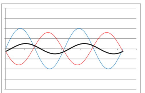
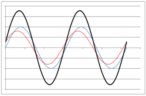
Multipath Propagation

Destructive interference
Constructive interference
Types of Fading
◆ Fast fading, Slow fading, Flat fading, Selective fading
◆ Rayleigh fading, Nakagami-m and Rician fading
Network Architecture
Cellular concept(蜂窝网络的概念)
40年代后期:AT&T开发了频率复用的蜂窝概念
◆ Break the service area into cells
◆ Shrink the cell size; adopt intensive frequency re-use
◆ Add more cells to add more capacity
◆ Mobility management is required
相邻的分区分为不同的载波,避免干扰(距离足够远有可能使用相同载波)
Radio access
该基站有3个扇区,每个扇区都配备独立的中继器(发射器/接收器)
它在每个扇区都有间隔对天线,以提供分集接收
微波将天线连接到网络
天线上的LNAs(LNA=低噪声放大器)
Diversity 分集
Different phase relations will exist between the multipath rays from each antenna – so the interference will be different.
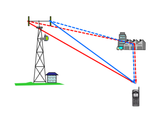
由于每个蜂窝的频率不同在传输中会造成频分(每个扇区对应不同的频率的载波)所以有多径问题会造成ISI
分集技术是研究如何充分利用传输中的多径信号能量,以改善传输的可靠性,它也是一项研究利用信号的基本参量在时域、频域与空域中,如何分散开又如何收集起来的技术

不同的分集中分的方式:
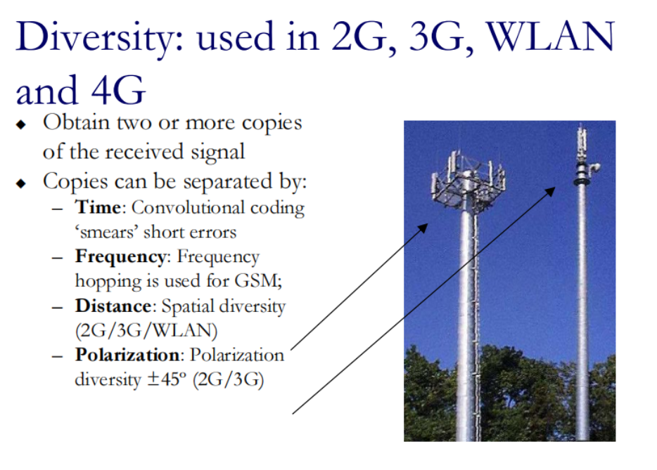
不同集(合并)的方式
分集增益Diversity gain,通过分集技术使信号功率增益了多少,以实现某些规定的可靠性。通常为4-6dB,具体取决于环境。
结合来自每个分支的信号,得到一个比任何单个分支都更可靠的信号
– Switch diversity 切换合并– when one is too low, try another 当一个太低时,试试另一个
– Selection diversity 选择式合并– choose the largest signal 选择最大的信号
– Equal gain 等增益合并 – signals equally weighted and added in phase
– Maximal ratio最大比合并 – weight the power in the branches in proportion to their signal amplitude and add in phase将支路中的功率按其信号振幅的比例加权,并加入相位
Frequency reuse
频率重用
◆ Adjacent cells use different frequencies to avoid interference
◆ Cells sufficiently distant from each other can use the same channel (frequency)
Control cell size by choosing BS power and antennas– Make use of topographical screening
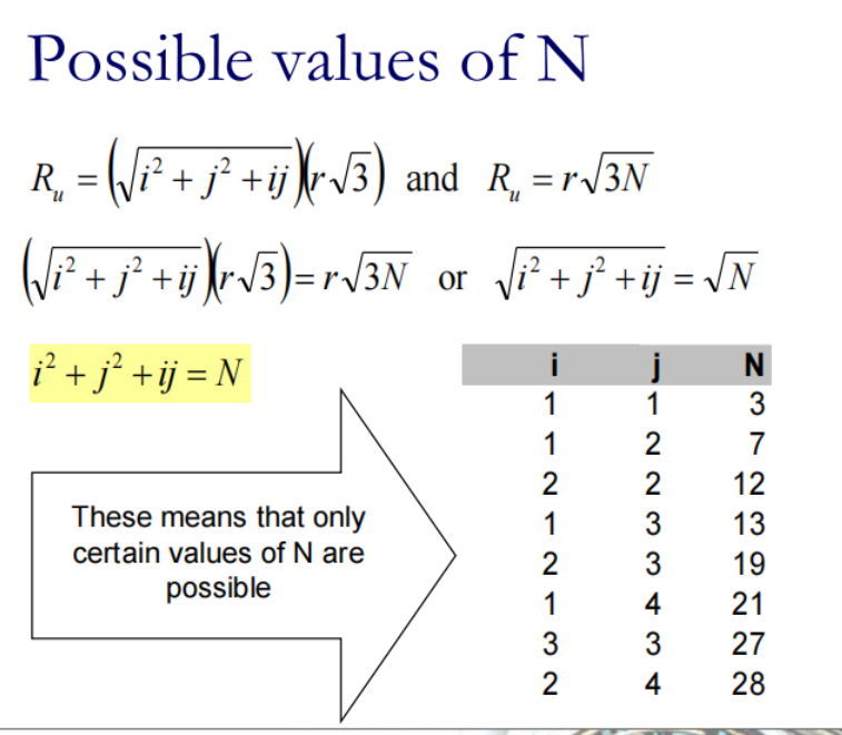
Reuse factor N: number of cells in a repeating pattern(一个小区簇里有几个使用不同频率的小区)
小区簇(cluster )是可以使用全部可用频率的最小小区(cell)集合,即在该集合内的小区使用不同的频率,而在该集合之外的小区可以使用对应的相同频率。小区簇中小区的个数即称为频率复用系数,有时也被称作频率复用因子,典型值为1、4、7、12。
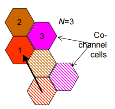
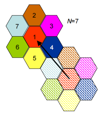
◆ Bigger cluster: less interference from next cell using the same frequency
– lower capacity – bandwidth available in cell is FA /N (FA is frequency spectrum allocated)
Reminders on Geometry
Surface area of a hexagon(六边形)=6*area of equilateral triangle
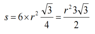
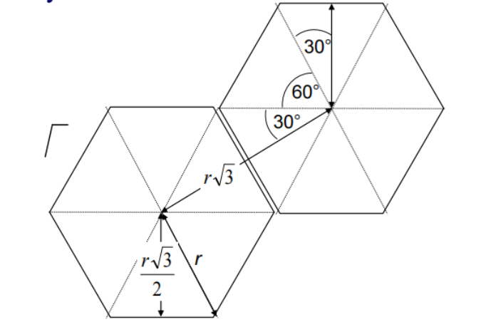

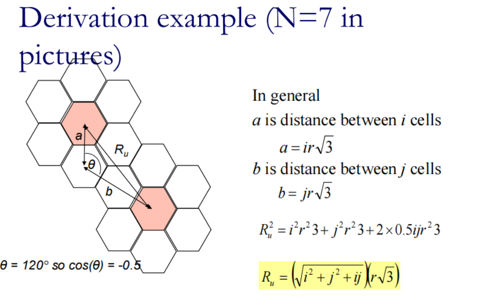
r是中心到cell顶点的距离
Ru是两个相同频率的cell的中心距离
从簇角度算:
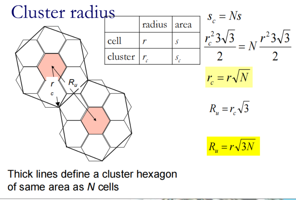
所以N只有下表中可能出现的值:
