07-timer
Timer Peripherals
How long does it take to execute an ARM instruction?
Different instructions requires different clock cycles to complete.
• CPI = Clock Per Instruction 每条指令所需时钟周期数
• For instance, CPI of MOV is 1 (unless move to PC).
ARM M3/M4是pipelined processor,因此可以并行执行多个指令以节省时间。因此,CPI并不固定(但是平均值是可计算的)
The actual timing of instructions can only be determined when the whole program is ready for simulation or analysis.
Time Delay Loop
Estimate the time taken to execute the following code snippet (in terms of clock cycles):
DELAY
	MOV r0, #250
LOOP
	SUBS r0, #1
	BNE LOOP
MOV指令需要1个时钟周期,SUBS指令需要1个时钟周期,BNE指令需要3个时钟周期
Time delay
~= 1 + 250 x (1 + 3)
~= 1001 cycles
This is approximate because of BNE.
DELAY
	MOV r0, #250
LOOP
	NOP
	NOP
	NOP
	NOP
	SUBS r0, #1
	BNE LOOP
NOP需要一个周期
Time delay
~= 1 + 250 x (1 x 4 + 1 + 3)
~= 2001 cycles
if CPU runs at 80 MHz, this takes approximate 25 μs to execute.
2001/80,000,000秒,约为25微秒(μs)
Longer Time Delay
可以实现精确的时间延迟
__asm void delay_cycles(unsigned int cycles){
LSRS r0, #2 // logic shift right 2 bits (/4)
BEQ done
loop // each time it takes 4 cycles
SUBS r0, #1
BNE loop
done
BX lr
}
Time delay = 1 + 1 + cycles/4 x (1 + 3) + 2 (assume BEQ not taken)= cycles + 4
一开始除4是因为后面循环里有四个周期的指令所以保证传入的参数为cycle
?????
实现一个任意长度的延时
The no. of cycles that can be waited is limited by the size of unsigned int = 32 bits in ARM M3/M4, so we need to calculate how many times we need to call delay_cycles(), depending on the clock frequency (SystemCoreClock in the code)
SystemCoreClock:频率,一秒中有几个周期
void delay_ms(unsigned int ms) {
unsigned int max_step =               //最多计时多少ms
1000 * (UINT32_MAX / SystemCoreClock);//乘以1000是为了将延迟时间从秒转换为毫秒
unsigned int max_sleep_cycles =
max_step * (SystemCoreClock / 1000); //最多记多少个时钟周期数
while (ms > max_step) {
ms -= max_step;
delay_cycles(max_sleep_cycles);
}
delay_cycles(ms * (SystemCoreClock / 1000));
}
SystemCoreClock是一个变量,它存储了当前系统的时钟频率
Timer: Concept

Based on presettable (i.e. load with a start value) binary counter
It is enhanced with configurability:
Count value can be read and written by the processor 可自定义计数
Count direction can often be set to up or down 可向上或者向下计数
Counter’s clock source can be selected
- Counter mode: count pulses which indicate events (e.g. odometer pulses)
- Timer mode: clock source is periodic, so counter value is proportional to elapsed time (e.g. stopwatch)
Counter’s overflow/underflow action can be selected
Generate interrupt
Reload counter with special value and continue counting
Toggle hardware output signal
Interrupt Timer

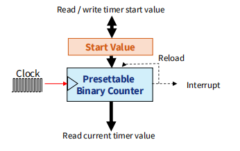
• Load start value from register
• Counter counts down with each clock pulse
• When timer value reaches zero
• Generates interrupt
• Reloads timer with start value
Calculating Start Value
计算初始值
Start value = round(T x Freq) - 1
T是所需的中断间隔(以秒为单位),Freq是时钟频率(以赫兹为单位)。由于定时器的计数器寄存器只能容纳整数值,因此此公式的结果应四舍五入到最近的整数。
• Example 1: interrupt every 137.41 ms, assuming clock frequency 24 MHz
• 137.41 ms x 24 MHz – 1 = 3297839 (happens to be integer)
• Example 2: interrupt with a frequency of 88 Hz with a 56 MHz clock
• round((1/88 Hz) x 46 MHz) - 1 = 522726
• actual frequency = 88.0000004591 Hz (very small error)
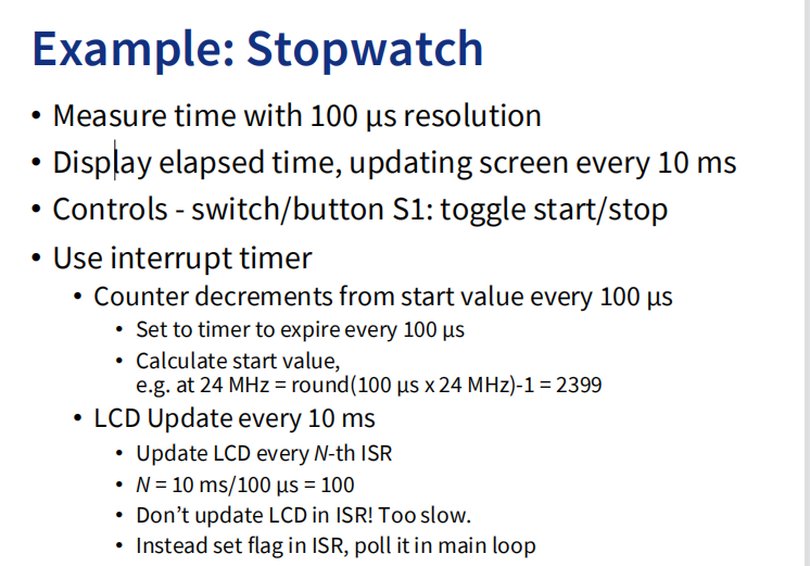
以100微秒的分辨率测量时间并显示经过的时间,每10毫秒更新屏幕。它使用中断定时器和一个计数器,每100微秒从起始值递减。定时器设置为每100微秒到期一次,并使用公式round(T x Freq) - 1计算起始值,其中T是所需的时间间隔,Freq是时钟频率。例如,在24 MHz的时钟频率下,100微秒时间间隔的起始值将为round(100微秒 x 24 MHz) - 1 = 2399。LCD在N-th ISR更新一次,其中N等于10毫秒/100微秒 = 100。为避免减慢ISR速度,在ISR中设置标志并在主循环中轮询该标志来更新LCD。
PWM Module (TPM)
Core Counter
- Clock options - external or internal (signal)
- Prescaler to divide clock (预分频分)
- Can reload with set value, or overflow and wrap around
Multiple channels - several modes
Capture Mode: Capture timer’s value when input signal changes
Output Compare: Change an output signal when timer reaches certain value.
输出比较模式。在输出比较模式下,当计时器达到指定值时,可以修改输出信号。可以设置、清除、脉冲或切换(反转)输出信号
PWM: Generate pulse-width-modulated signal. Width of pulse is proportional to specified value.
Possible triggering of interrupt, hardware trigger on overflow
One I/O pin per channel
Major Channel Modes
- Input Capture Mode
捕获模式。在捕获模式下,计时器会在输入信号发生变化(上升沿、下降沿或两者)时捕获计时器的值。这种模式可以回答一个问题:“我启动计时器后多久输入信号发生变化?”因此,它有效地测量时间差异。
Output Compare Mode
Modify output signal when timer reaches specified value Set, clear, pulse, toggle (invert)
Make a pulse of specified width
Make a pulse after specified delay
Output Compare Mode 是一种计时器模式,用于比较计时器的值和预设的比较值。当计时器的值与比较值相等时,可以执行一些操作,例如生成输出信号或调用中断。在Output Compare Mode中,可以设置不同的操作类型,例如Toggle、Clear和Set等。
- Pulse Width Modulation
Make a series of pulses of specified width and frequency
Input Capture Mode

I/O pin operates as input on edge
• When valid edge is detected on pin…
• Current value of counter is stored
• Interrupt is called
当有效边沿到来时,启动中断,并保存当前值
当计时器捕获到输入信号的状态变化时,会触发一个中断,并将当前计数器的值保存下来。
Output Compare Mode

设置比较值来控制输出信号的变化方式,如切换、清除或设置等。
Action on match
• Toggle
• Clear
• Set
When counter matches value …
• Output signal is generated
• Interrupt is called (if enabled)
Pulse Width Modulation (PWM)
• Digital power amplifiers are more efficient and less expensive than analog power amplifiers
• Applications: motor speed control, light dimmer, switch-mode power conversion
• Load (motor, light, etc.) responds slowly, averages PWM signal
• Digital communication is less sensitive to noise than analog methods
• PWM provides a digital encoding of an analog value
• Much less vulnerable to noise
PWM signal characteristics
• Fixed modulation frequency fmod how many pulses occur per second
固定的调制频率fmod,即每秒发生多少个脉冲
• Period: 1 / fmod
• On-time: amount of time that each pulse is on (asserted)
• Duty-cycle: on-time/period
• Adjust on-time (hence duty cycle) to represent the analog value
占空比为高电平时间与周期时间之比,可以通过调整高电平时间来改变占空比,从而实现对外设的控制。

PWM duty cycle proportional to compare value 占空比和比较值成正比
• Period = max timer value(最多能记多少数)
• On-time = compare value(设定的比较值)

Servo Motor
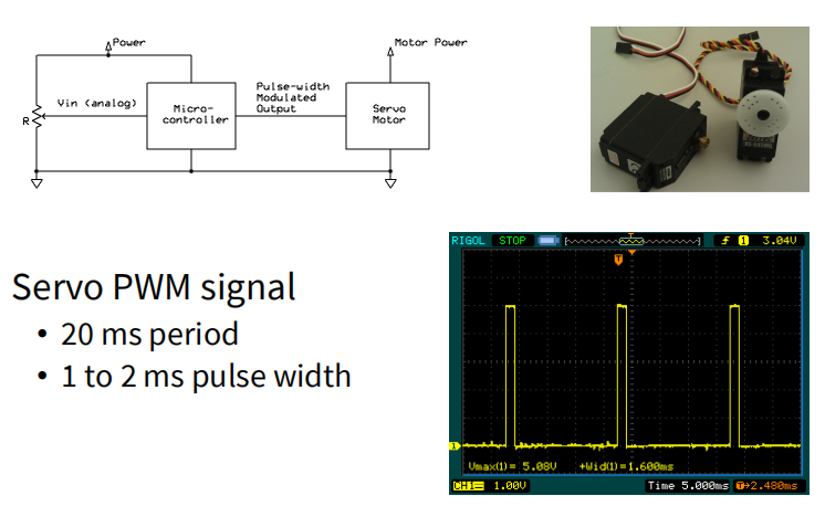
在PWM模式下,可以通过改变比较值来控制输出信号的高电平时间,从而控制伺服电机的转动角度。具体地说,PWM信号的周期为20ms,高电平时间在1ms到2ms之间变化,对应着伺服电机转动角度在0度到180度之间变化。
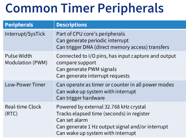
Low Power Timer

•特点
•计数时间或外部脉冲 当计数器匹配比较值时产生中断
•中断从低功耗模式唤醒MCU
•电流绘制可以降低到微安甚至纳安!
Use the WFI (Wait For Instruction) instruction (__WFI() in C)
• Puts CPU in low power mode until interrupt request
Programming SysTick and Interrupt in C (with CMSIS)
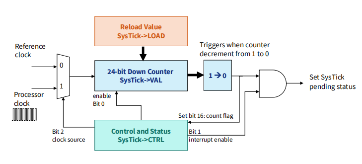
Cortex-M processors have a small integrated timer called the SysTick (System Tick) timer. Cortex‐M3 处理器内部包含了一个简单的定时器。因为所有的 CM3 芯片都带有这个定时器,软件在不同 CM3 器件间的移植工作得以化简。
- Part of NVIC, generating SysTick interrupt.
SysTick timer is a simple ==decrement== ==24-bit== timer.
- either on processor clock frequency 处理器时钟频率, or
- a reference clock frequency (e.g. on-chip clock source 片上时钟源)
Systick 是 STM32 的一个系统定时器,又名系统嘀嗒定时器,是一个 24 位的倒计数定时器,当计数到 0 时,将从 RELOAD 寄存器中自动重装载定时初值,开始新一轮计数。
It is common in modern OS that we need a periodic interrupt to execute the OS kernel.
Even without an OS, SysTick can be used for periodic interrupt generation, delay generation, or timing measurement.
即使没有操作系统,SysTick也可以用于周期性中断生成、延迟生成或时间测量。
SysTick timer has 4 registers.
• The data structure SysTick is defined in CMSIS to access them easily.
SysTick定时器在CTRL寄存器的第0位启用。当SysTick计数器减为0时,它将从VAL寄存器中加载一个新值,并继续计数。
VAL寄存器是SysTick定时器的当前值寄存器,它保存了当前的计数值。

控制及状态寄存器(CTRL)

重装载数值寄存器(LOAD)

几个周期
当前数字寄存器(VAL)

校准数值寄存器(CALIB)
Using the SysTick Timer (CMSIS)
The easiest way to generate a period SysTick interrupt is to use this CMSIS-Core fuction:
uint32_t SysTick_Config(uint32_t ticks);The function sets the interrupt interval to ticks, enables the counter using processor clock and enables the SysTick exception with lowest priority.
将中断周期设置为ticks,并使用处理器时钟启用计数器和SysTick异常,优先级最低。
优先级最低,因此其他中断可以在SysTick异常之前被处理。
Example: if you want to trigger a SysTick exception of 1 kHz,
SysTick_config(SystemCoreClock / 1000);SystemCoreClock:系统周期,对应频率1HZ,除1000,对应频率1000Hz
Then SysTick_Handler(void) is triggered at a rate of 1 kHz
Writing to SysTick registers
如果你想使用参考时钟源或不触发中断,你可以直接写到SysTick寄存器。
在“SysTick->CTRL”中输入“0”,关闭SysTick定时器。(以防之前已启用)
将新的加载值写入 SysTick->LOAD 重新加载值应该是(间隔值- 1)。
写入SysTick当前值寄存器 SysTick->VAL 清除当前值为0。
写入到SysTick控制和状态寄存器 SysTick->CTRL 启动SysTick定时器
A simple C example of polling SysTick value for timed delay.
SysTick->CTRL = 0; 		// stop SysTick
SysTick->LOAD = 0xFF; 	// count 255+1=256 cycles
SysTick->VAL = 0;
SysTick->CTRL = 5; //使能+内核时钟

// wait until count flag is set
while ((SysTick->CTRL & 0x00010000) == 0);
//16bits变为1
SysTick->CTRL = 0; 	// stop SysTick
Building Driver for SysTicks
- 设置每(timestamp)μs触发一个interrupt
timer_init(timestamp);- 设置Interrupt handler
timer_set_callback(timer_isr);- 启动SysTicks
timer_enable()- 关闭SysTicks
timer_disable()timer_init()
void timer_init(uint32_t timestamp) {
	uint32_t tick_us = (SystemCoreClock)/1e6;
	tick_us = tick_us*timestamp;
	SysTick_Config(tick_us);
	//NVIC_SetPriority(SysTick_IRQn, 3);
}
Explanation:
- Calculate how many cycles for each millisecond
- Multiply with timestamp to get required interval (in cycles)
- Configure the interval using SysTick_Config()
- Change interrupt priority if needed
Enable/Disable Timer
Start and stop the timer by setting/clearing the right bits
void timer_enable(void) {
SysTick->CTRL = SysTick_CTRL_CLKSOURCE_Msk |
				SysTick_CTRL_TICKINT_Msk |
				SysTick_CTRL_ENABLE_Msk;
}
将三个bit初始化
void timer_disable(void) {
SysTick->CTRL &= ~SysTick_CTRL_ENABLE_Msk;
}
只将enable设为0
• start: processor clock, enable interrupt and enable timer
• stop: disable timer (clear bit 0)
• All bit masks (e.g. SysTick_CTRL_CLKSOURCE_Msk) are defined for compatibility (and no need to remember exact bit no.)
Set up a pointer to function for the interrupt service routine
static void (*timer_callback)(void) = 0;
void timer_set_callback(void (*callback)(void)) {
timer_callback = callback;
}
void SysTick_Handler(void){
timer_callback();
}
用户通过调用timer_set_callback()提供一个指向回调函数(实际的ISR)的指针。让timer_callback指向ISR
当计时器中断发生时,SysTick_Handler()被调用,然后它访问回调的指针并调用函数。
使用实例 Flashing an LED
void toggle_led(void){
	gpio_toggle(LED_PIN);
}
void main(void) {
	timer_init(100000); // 100 ms = 100000 us
	timer_set_callback(toggle_led);
	timer_enable();
	__enable_irq();
	while (1)
	__WFI();
}__enable_irq(): The function enables interrupts and all configurable fault handlers by clearing PRIMASK.__WFI()suspends execution until one of the following events occurs (put in low power mode). But the while loop can be replaced by other tasks to be run in parallel.


