02-ARM Cortex-M4
ARM Cortex-M4
What is ARM Architecture?
ARM architecture is a family of RISC(精简指令集)-based processor architectures
CISC计算机使用
先进的RISC机器
以其电源效率而闻名;
因此被广泛应用于移动设备,如智能手机和平板电脑
由ARM设计并授权给广泛的生态系统
- ARM Holdings
•该公司设计基于arm的处理器;
•不制造,但将设计授权给半导体合作伙伴,后者将自己的知识产权(IP)添加到ARM的IP之上,制造并销售给客户;
•提供除处理器之外的其他IP,如物理IP、互连IP、图形核心和开发工具。
在一家公司获得了Cortex-M处理器设计的授权后,ARM则会以Verilog-HDL(硬件描述语言)语言的形式提供设计的源代码。这些公司中的设计工程师随后会将外设和存储器等他们自己的设计模块添加进来,并且使用各种EDA工具将整个设计从Verilog-HDL和其他多种形式转换为晶体管层级的芯片设计。
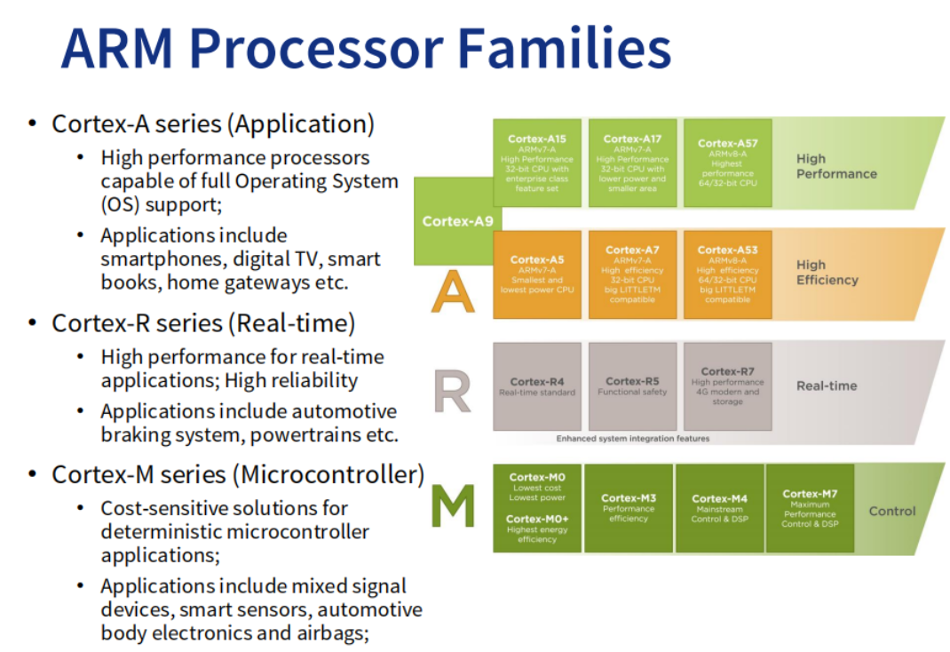
Processor Families

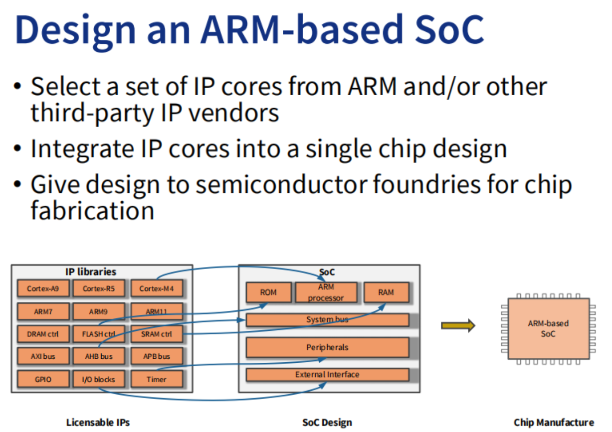
Design an ARM-based SoC(片上系统)
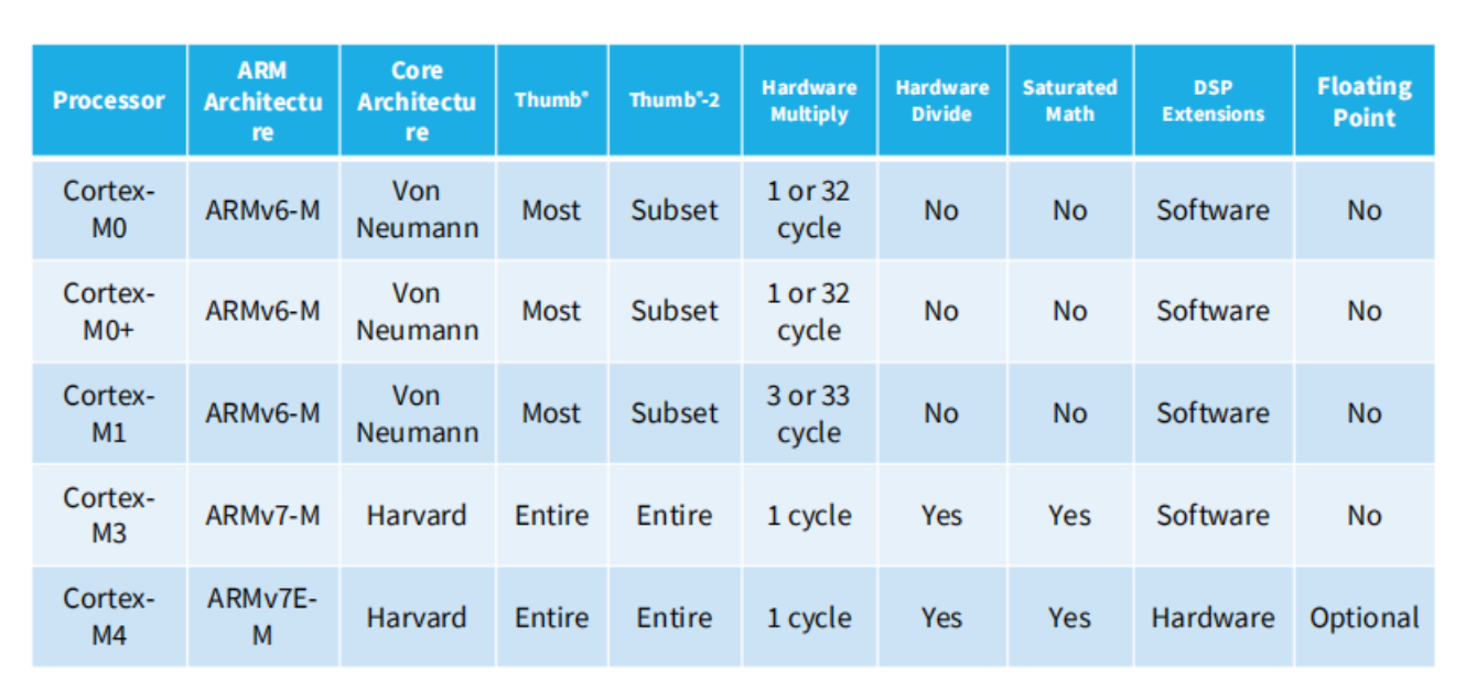
ARM Cortex-M Series
Cortex-M series: Cortex-M0, M0+, M1, M3, M4.
- Energy-efficiency
• Lower energy cost, longer battery life
与其他32位微控制器设计相比,Cortex-M处理器相对较小。Cortex-M处理器也进行了低功耗的优化
Smaller code
更低的硅成本
Ease of use(易于使用)
Faster software development and reuse
Cortex-M处理器具有简单、线性的存储器映射
Embedded applications
智能计量,人机界面设备,汽车和工业控制系统,白色家电,消费品和医疗仪器
ARM Processors vs. ARM Architectures
ARM architecture
• Describes the details of instruction set, programmer’s model, exception model, and memory map 描述指令集、程序员模型、异常模型和内存映射的细节 是公司的设计
ARM processor
• Developed using one of the ARM architectures
• More implementation details, such as timing information
ARM Cortex-M4 Processor Overview
High Performance Efficiency
• 1.25 DMIPS/MHz (Dhrystone Million Instructions Per Second / MHz) at the order of µWatts / MHz(Dhrystone是测量处理器运算能力的最常见基准程序)
word size:32-bit Reduced Instruction Set Computing (RISC) processor
每次取指令都是32位的,而多数指令则是16位的,因此一次可以取两条指令,存储器接口上的多余带宽也带来了更高的性能和更佳的能耗效率。
Harvard architecture(data 和 instruction分离,可以同时fetch)
Low Power Consumption(低功耗)
3-stage(fetch+Decode+excute) + branch speculation pipeline
三级流水线结构使得包括乘法在内的多数指令,可以在单周期内执行,
Supported Interrupts
• Non-maskable Interrupt (NMI) + 1 to 240 physical interrupts
• 8 to 256 interrupt priority level(中断和多个系统异常具有可编程的优先级)
支持最多240个中断输入、不可屏蔽中断(NMI)输入和多个系统异常。每个中断(NMI除外)都可以被单独使能或禁止。
Supports Sleep Modes
Up to 240 Wake-up Interrupts
Enhanced Instructions
• Hardware Divide (2-12 Cycles)
• Single-Cycle 16/32-bit MAC, Single-cycle dual 16-bit MAC
Memory Protection Unit (MPU)
Optional 8 region MPU with sub regions and background region
Cortex-M4 Block Diagram
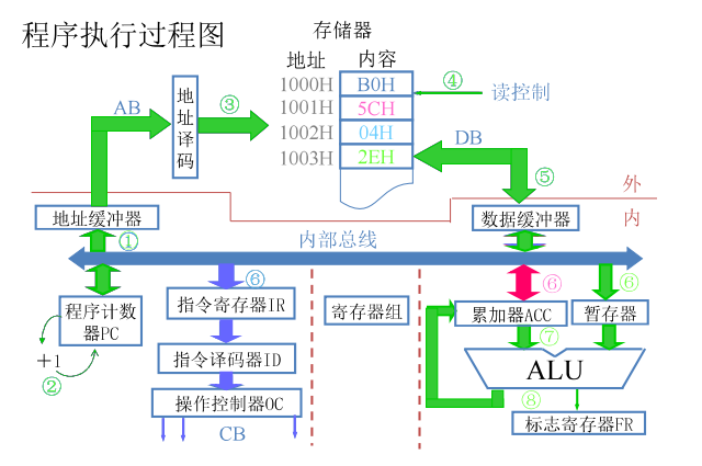
Processor pipeline stages
• Three-stage pipeline: fetch, decode, and execution
• Some instructions may take multiple cycles to execute, in which case the pipeline will be stalled
• The pipeline will be flushed if a branch instruction is executed
• Up to two instructions can be fetched in one transfer (16-bit instructions)
word set是32bit所以一个时间可以fetch两条instruction,但是每次只能执行一次decode

尽可能的填满cpu:提升使用效率
Bus interconnect
Allows data transfer to take place on different buses simultaneously
Provides data transfer management,同时读内存和指令
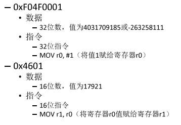
数据与指令
寄存器里既可以存数据也可存指令
Registers
The internal registers are used to store and process temporary data within the processor core.
All registers are inside the processor core, hence they can be accessed quickly.
Load-store architecture
对于ARM架构,若处理的是存储器中的数据,就需要将其从存储器加载到寄存器组中的寄存器里。在处理器内处理完后,若有必要,还要写回存储器,这种方式一般被称作“加载一存储架构”
Register bank(寄存器组)
寄存器组中有16个寄存器,其中13个为32位通用目的寄存器,其他3个则有特殊用途
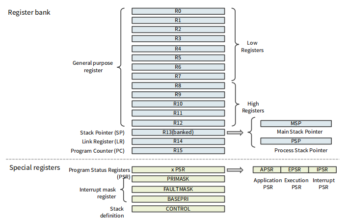
R0~R12
general purpose registers
Low registers (R0 – R7) can be accessed by any instruction
High registers (R8 – R12) sometimes cannot be accessed(用于32位指令和几个16位指令)
R13: Stack Pointer (SP)
栈指针
• Records the current address of the stack
两个栈指针:
主栈指针(MSP)为默认的栈指针,在复位后或处理器处于处理模式时,其会被处理器选择使用。另外一个栈指针名为进程栈指针(PSP),其只能用于线程模式
R14: Link Register (LR)
链接寄存器(LR)
store the return address of a subroutine or a function call函数或子程序调用时返回地址的保存
The program counter (PC) will load the value from LR after a function is finished
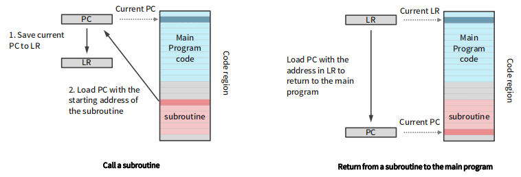
调用子程序时,先将pc存到LR中,如何让pc指向要调用的程序,最后将LR中地址覆盖回去当执行了函数或子程序调用后,LR的数值会自动更新
R15: Program Counter (PC)
R15为程序计数器(PC)
Records the address of the next instruction for execution
每次操作自动加4(对于32位指令代码),分支操作除外
xPSR, combined Program Status Register
组合程序状态寄存器
组合程序状态寄存器包括以下三个状态寄存器Provides information about program execution and ALU flags:
应用 Application PSR(APSR)
执行 Interrupt PSR(EPSR)
中断 Execution PSR(IPSR)

这三个寄存器可以通过一个组合寄存器访问
APSR
N: negative flag – set to one if the result from ALU is negative
Z: zero flag – set to one if the result from ALU is zero
C: carry flag – set to one if an unsigned overflow occurs
C:进位/借位标志。表示在加法/减法运算中,产生了进位/借位。
V: overflow flag – set to one if a signed overflow occurs
Q: DSP overflow and saturation flag – set to one if saturation has occurred in saturating arithmetic instructions, or overflow has occurred in certain multiply instructions
IPSR
• ISR number – current executing interrupt service routine number
包含了当前正在执行的中断服务程序编号
EPSR
• T: Thumb state – always one since Cortex-M4 only supports the Thumb state (more on processor states in the next module)
• IC/IT: Interrupt-Continuable Instruction (ICI) bit, IF-THEN instruction status bit
Interrupt mask registers
• 1-bit PRIMASK
Set to one will block all the interrupts apart from non-maskable interrupt (NMI) and the hard fault exception
• 1-bit FAULTMASK
Set to one will block all the interrupts apart from NMI
• 1-bit BASEPRI
Set to a non zero value will block all interrupts of the same or lower level (only allow for interrupts with higher priorities)
CONTROL: special register
1-bit stack definition
Set to one: use the process stack pointer (PSP)
Clear to zero: use the main stack pointer (MSP)
Cortex-M4 Memory Map
存储器映射
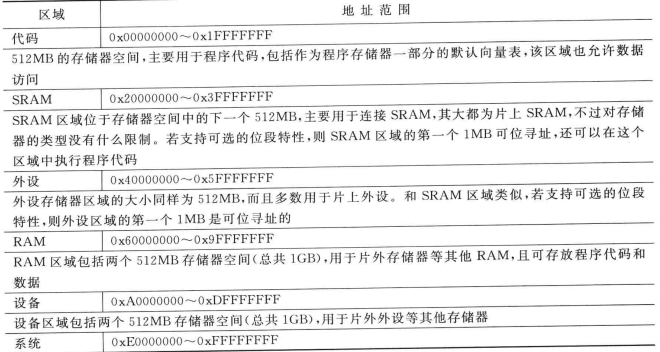
Cortex-M4 processor has a 4GB memory space(32Byte=$2^2*2^{30}$), which is architecturally defined as a number of regions
1word=4byte(32bits)内存地址以字节为单位
arm中可以编址的最小单元是字存储单元,则该计算机称为按字寻址的计算机(4byte)每一个寄存器都是占用4个字节即32位
4GB的存储器空间被划分为多个区域,用于预定义的存储器和外设,以优化处理器设计的性能
• Each region is given for recommended usage
• Easy for software programmer to port between different devices
尽管存在默认内存映射,但用户可以灵活地定义内存映射的实际使用情况
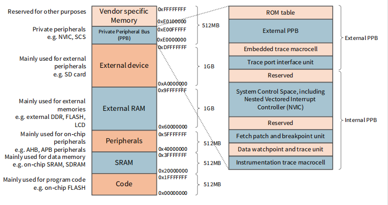
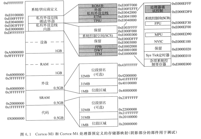
Code Region
• Primarily used to store program code Can also be used as memory for constant data On-chip memory, such as on-chip FLASH
保存代码和常数
SRAM Region
store data, such as heaps and stacks
Can also be used for program code
可读写数据和堆栈
尽管它的名字是“SRAM”,但实际的设备可能是SRAM、SDRAM或其他类型
Peripheral Region外设
主要通过高级高性能总线(AHB)或高级外设总线(APB)外设用于片上外设
External RAM Region
可以用来存储大数据块,或者是芯片外存储器中的内存缓存
slower than on-chip SRAM region
External Device Region
is used to map to off-chip external devices such as SD card‘
Internal Private Peripheral Bus (PPB)
Used inside the processor core for internal control
Within PPB, a special range of memory is defined as System Control Space (SCS)
嵌套矢量中断控制器(NVIC)是SCS的一部分
Bit-band Operations
位段操作
利用位段操作,一次加载/存储操作可以访问(读/写)一个位
To change a single bit of one 32-bit data
Normal operation (read-modify-write procedure)
•读取32位数据的值
•修改单个位,同时保持其他位不变(掩码)
•将32位值写回相同的地址
Bit-band operation
直接将单个位(0或1)写入数据的“bit-band alias address”
Bit-band alias address
• Each bit-band alias address is mapped to a real data address
• When writing to the bit-band alias address, only a single bit of the data will be changed
• For example, in order to set bit[3] in word data in address 0x20000000:
;Read-Modify-Write Operation
LDR R1, =0x20000000 ;Setup address
LDR R0, [R1] ;Read
ORR.W R0, #0x8 ;Modify bit(or:或上一个0...01000(0x8)改变位)
//ORR 或
STR R0, [R1] ;Write back
;Bit-band Operation
LDR R1, =0x2200000C ;Setup alias(把要改的bit的地址存好)
MOV R0, #1 ;Load data(改后的结果)
STR R0, [R1] ;Write back(覆盖掉)把R0存到R1存的地址na'lEach bit of the 32-bit data is one-to-one mapped to the bit band alias address
当使用位段别名地址时,每个位都可以通过对应的字对齐地址的最低位(LSB)单独访问

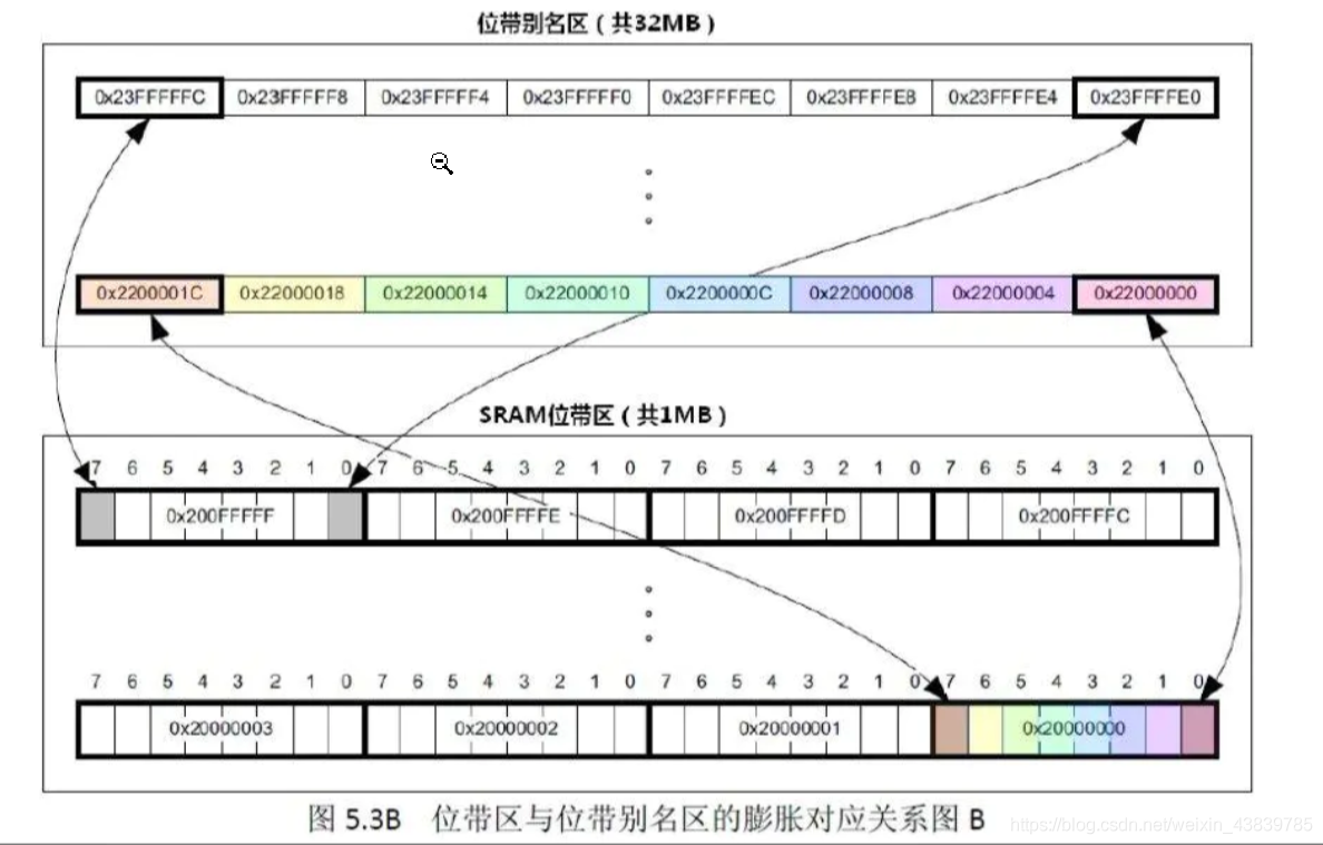
相邻32-bite data在地址上相差4byte,每个字段中的每个bit是没有对应地址的(一个字段只能占用四个地址(每个字节占用一个)如上图最后一行)所以想访问每个bit需要位带别名(每个bit被一个长为4byte地址表示(1bit数据地址用32bit表示),arm规定相邻bits的位带别名相差4bits)
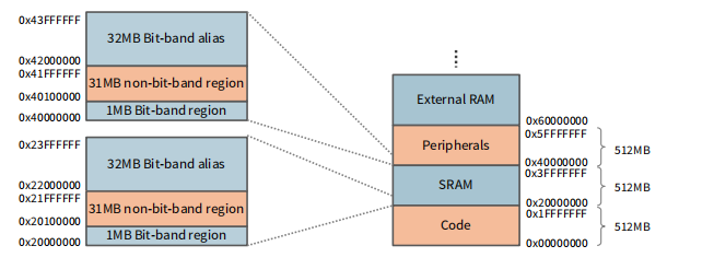
所以在SRAM region和Peripherals region
都有1MB的数据对应32MB的Bit-band alias,另外有31MB的数据没有Bit-band alias?

Benefits of Bit-Band Operations
• Faster bit operations
• Fewer instructions
• Atomic operation, avoid hazards
如果在Read-Modify-Write操作期间触发并服务中断,并且中断服务例程修改相同的数据,则会发生数据冲突

Cortex-M4 Program Image
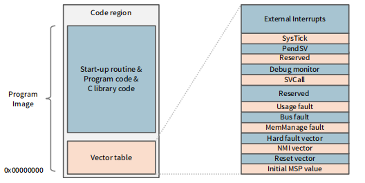
code部分:
• Vector table – includes the starting addresses of exceptions (vectors) and the value of the main stack point (MSP);
• C start-up routine;
• Program code – application code and data;
• C library code – program codes for C library functions.
Reset Behaviour
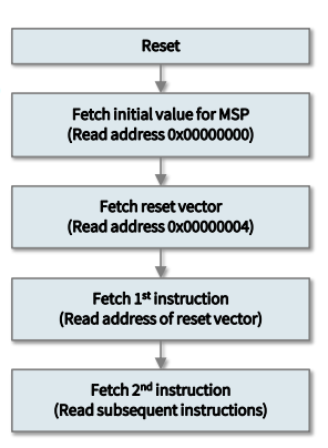
After reset, the processor:
reads the initial MSP(主栈指针,此时为0x00000000) value to set up the stack
Then reads the reset vector(跳转到其它程序)
分支到程序执行地址的开始(复位处理程序);
Subsequently executes program instructions
Cortex-M4 Endianness字节顺序
Endian refers to the order of bytes stored in memory
• Little endian: lowest byte of a word-size data is stored in bit 0 to bit 7 低对低,高对高
1个字节是8个比特是两个十六进制数

这个两字节的数存放在0x1002(低位字节的地址)

这个四字节的数存放在0x100(最低字节的地址为这个数的地址)
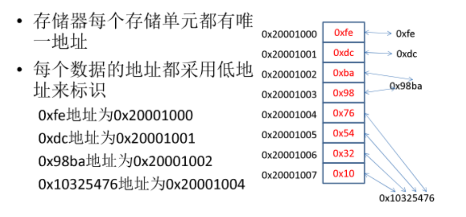
• Big endian: lowest byte of a word-size data is stored in bit 24 to bit 31

Cortex-M4 supports both little endian (default) and big endian.
ARM Cortex-M4 Processor Instruction Set
Mix of ARM and Thumb-1 Instruction sets
Benefit from both 32-bit ARM (high performance) and 16-bit Thumb-1 (high code density)
A multiplexer is used to switch between two states: ARM state (32-bit) and Thumb state (16-bit)

thumb要先映射给arm
Thumb-2 instruction set

不用选择器
M4 Instructions
Cortex-M4 processor Supports 32-bit Thumb-2 instructions
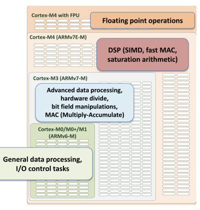
M4能干M3的事
The Assembly Language Syntax
label
mnemonic operand1, operand2, … ; Commentslabel:optional,reference to an address location(地址位置)
label后为mnemonic(助记符),也就是指令的名称,其后跟着的是多个操作数
operand1: 目的地
operand2:源
目的在前源在后
对于在ARM汇编器中编写的数据处理指令,第一个操作数为操作的目的。
对于存储器读指令(多加载指令除外),第一个操作数为数据被加载进去的寄存器。
对于存储器写指令(多存储指令除外),第一个操作数为保存待写人存储器的数据的寄存器。
mnemonic后面有可能有不同类型的operand,This can result in different instruction encodings
指令中操作数的个数取决于指令的种类,而操作数的语法也可能会各不相同。
Immediate data前缀**#**、

Immediate data(立即数)
(prefix with #): a simple way to get data is to make the data part of the instruction
MOVS R0, #0x12 ; Set R0 = 0x12 (hexadecimal)
MOVS R1, #'A' ; Set R1 = ASCII char A
Suffix
对于ARM处理器的汇编器,有些指令后会跟着后缀(加在mnemonic后面)。

MOVS R0, R1 ; move R1 into R0, update APSR
MOV R0, R1 ; move R1 into R0, not update APSR
Moving data within the processor
微处理器中最基本的操作是在处理器内部移动数据
• Move data from one register to another
• Move an immediate constant into a register
; Copy value from R0 to R4
MOV R4, R0
; Set R3 value to 0x34 and update APSR
MOVS R3, #0x34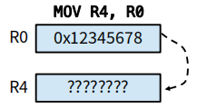
Data Size in Memory Access Instructions
• The default data size for memory access is 32 bits.
• If you wish to transfer 8 bits (1 byte), add suffix B.
• If you wish to transfer 16 bits (2 bytes), add suffix H.(half word)
• If the source data is considered signed and sign extension is needed, suffix by S (for loading) 只有LDR中的S是sign意思
LDRSB R0, [R1, #3]		;将内存单元R1+3中的有符号字节数据读取到R0中,R0中高24位设置成该字节数据的符号位
LDRSB R7, [R6, #-1]!	;将内存单元R6-1中的有符号字节数据读取到R7中,R7中高24位设置成该字节数据的符号位,R6 = R6 - 1
LDR指令主要用于储存加载数据到寄存器Rx中,也可以将一个立即数加载到寄存器Rx中,LDR加载立即数要使用“=”。而不是“#”
LDR从存储器读取数据,STR是将数据写入存储器中。
; load/store 32 bits to/from R1 from/to memory addr R0
LDR R1, [R0] ;读取地址R0中的数据到R1寄存器中
STR R1, [R0] ;将R1中的值写入到R0中所保存的地址中
; load/store 8 bits, unsigned (padded with 0's)
LDRB R1, [R0]
STRB R1, [R0]
; load/store 16 bits, signed (signed extended)
LDRSH R1, [R0]
STRH R1, [R0]
括号的重点是访问内存。可以将其视为C中的*运算符(访问地址的值)
Arithmetic Operations
微控制器的应用通常涉及对数据进行数学计算,以改变程序流程和修改程序动作。
; R0 = R0 + R1
ADD R0, R0, R1
; R0 = R0 + 0x12 with APSR (flags) update
ADDS R0, R0, #0x12
; R0 = R1 + R2 + carry
ADC R0, R1, R2
在减法中,进位作为借位,从SBC中的差值中减去。
; R1 = R3 - R2
SUB R1, R3, R2
; R0 = R1 – 0x26 – not(carry)
SBC R0, R1, #0x26
; R0 = R1 * R2
MUL R0, R1, R2
; R0 = R1 / R2 (unsigned or signed)
UDIV R0, R1, R2
SDIV R0, R1, R2x = 2x – y + 3
; x in R0; y in R1
LDR R0, =0x0A ; test value x
LDR R1, =0x05 ; test value y
ADDS R0, R0, R0 ; 2x
SUBS R0, R0, R1 ; 2x - y
ADDS R0, R0, #3 ; 2x - y + 3

