06-Serial Communication (UART)
Serial Communication (UART)
Serial vs Parallel
Serial: one bit is presented per cycle (N clock periods)
Parallel: N bits together at a cycle (1 clock period)
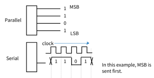
Serial Communication
如果你想尽量减少连接两个系统的数据线的数量,那么串行通信是首选。
Tradeoff: the latency/efficiency is lower
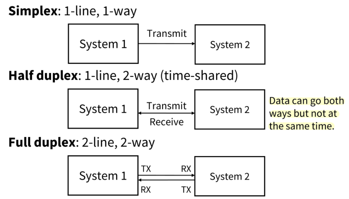
3种模式
Simplex:单向的,固定一个发一个收
Half Duplex:是双向传输但是不能同时进行
Full Duplex:可以同时双向收发
同步
传输的时一个二进制数据流,即一个“0”或“1”的序列
- 发送端:encode the stream
- 例如,
'A' = 0x41=b"01000001"
- 例如,
- 接收端:decode the stream
- 为了成功通信,系统在传输过程中必须保持同步。
两种传输方法:
- ==Synchronous==:系统使用统一的时钟
- ==Asynchronous==:系统使用分开的时钟
Synchronous Transmission
==依靠信号中的时钟分量来保持时钟一致==
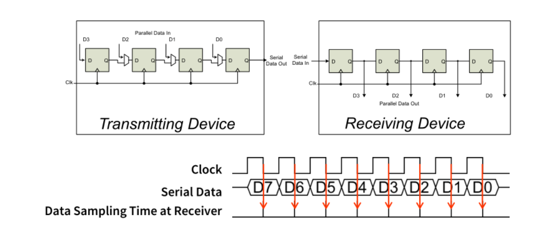
- 使用移位寄存器和一个时钟信号完成串并转换
同步:与数据信号一起的称为explicit clock(显式时钟信号)
an explicit clock signal is along with the data signal
Asynchronous Transmission
==使用不同的时钟==Separate clocks
- 正确解码的前提:接收机必须与发射机同步采样。
在实际中,时钟会因为error而出现错误
- 所以,我们必须定期重新同步以确保时钟保持同步。
为了解决同步问题,我们使用==Asynchronous Communication Protocol==
Asynchronous Comm. Protocol
串行通信协议,其原理是将数据编码成一个个帧,包含起始位、数据位和停止位。起始位用于接收方同步,数据位用于传输数据,停止位表示帧的结束。
- Start bit:接收器同步的起始位(感应到这个就开始同步)
- Data bits:传输的word的data
- Stop bit:表示该帧已传输完
==Frame与Frame之间保持高电位==(IDLE)【空闲状态保持高电平】。

接收机检测Start bit前沿,然后将其作为采样数据线的timing reference,在时间$T_{bit}*(N+1.5)$内提取N个数据比特

difference
对于8位数据,我们可以容忍大约5%的时钟速度差异。

Data Frame格式
Start bit:1个bit
Data:LSB最先,总长度为7-9个bits
Parity Bit:(可选)用于检测数据中是否有error
Stop bit:1个bit或者2个bits

串口通信速率
All devices must use the same communications parameters
所有设备必须使用相同的通信参数
- 例如通信速度(300波特、600、1200、2400、9600、14400、19200等)
Sophisticated network protocols have more information in each data
frame
• Medium access control – when multiple nodes are on bus, they must arbitrate for permission to transmit
• Addressing information – for which node is this message intended?
• Larger data payload
• Stronger error detection or error correction information
• Request for immediate response (“in-frame”)
Error Detection
Can send additional information to verify data was received correctly
Need to specify which parity to expect: even, odd or none(指定校验模式)
补一位使1的个数为奇数——奇校验
为偶数——偶校验
• 01110111 has 6 “1” bits, so parity bit will be 1 for odd parity, 0 for even parity
• 01100111 has 5 “1” bits, so parity bit will be 0 for odd parity, 1 for even parity
Single parity bit detects if 1, 3, 5, 7 or 9 bits are corrupted, but doesn’t detect an even number of corrupted bits
只有发生奇数个错误时候,才能检测到,偶数个无法检测
Stronger error detection codes (e.g. Cyclic Redundancy Check) exist and use multiple bits (e.g. 8, 16), and can detect many more corruptions.


• Advantages: simple & inexpensive
• Disadvantages: high overhead because of start and stop bits: 2 / 10 (or more) of bandwidth.
synchronous communication protocol
A common clock signal solves synchronisation problem: more efficient (but more complex) than asynchronous
separate clock and data lines
encode clock in the data steam e.g. Manchester coding
Asynchronous protocol – RS232C
RS232C: Recommended Standard number 232 revision Commonly used asynchronous standard
It specifies voltages in Reversed Polarity.(电压反极性表示)
-3V to -15V = “Mark” or Logic ‘1’
3V to 15V = “Space” or Logic ‘0’
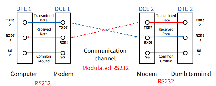
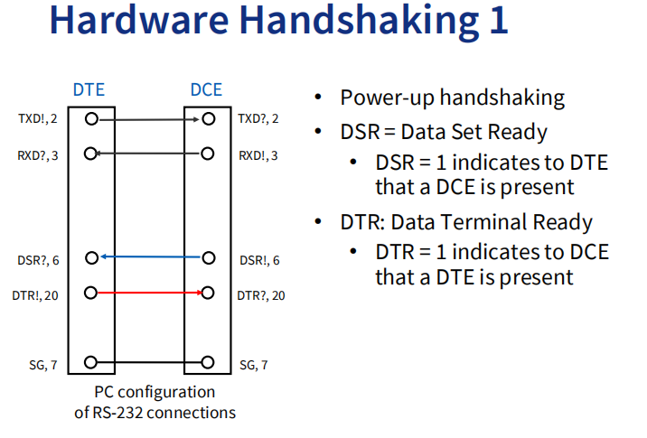
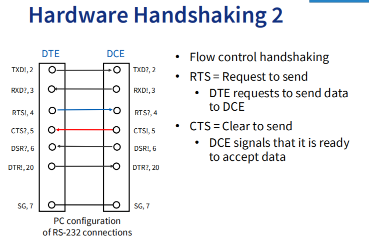
DTE = Data Terminal Equipment
DCE = Data Communications Equipment
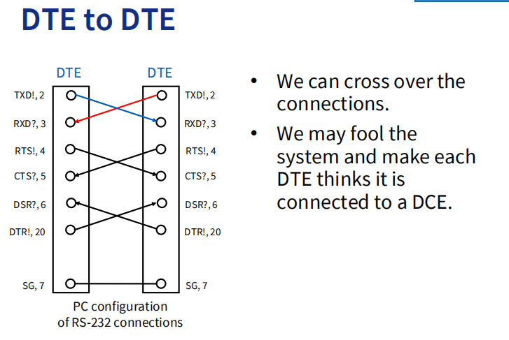
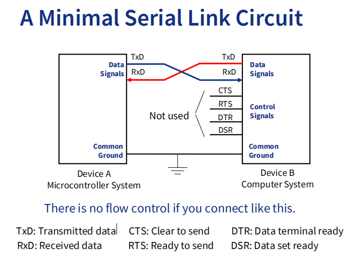
Full duplex communication link between DTE1 and DTE2.
DTE1 TXD is effectively connected to DTE2 RXD.
DTE2 TXD is effectively connected to DTE1 RXD
RS232C: Flow Control
一次传太多会使接收端buffer溢出
Request-to-send (RTS) and clear-to-send (CTS) allow hardware control of the data flow.
Parsing Messages – decoding content from received BITs
Two types of messages:
• Actual binary data sent
• First identify message type
• Second, based on this message type, copy binary data from message fields into variables
• May need to use pointers and casting to get code to translate formats correctly and safelyASCII text characters representing data sent
• First identify message type
• Second, based on this message type, translate (parse) the data from the ASCII message format into a binary format
• Third, copy the binary 将二进制数据复制到变量中
==第一步都是要识别消息类型==
Example Binary Serial Data: TSIP
switch (id) {
case 0x84:
lat = *((double *)(&msg[0]));
lon = *((double *)(&msg[8]));
alt = *((double *)(&msg[16]));
clb = *((double *)(&msg[24]));
tof = *((float *)(&msg[32]));
break;
case 0x4A: …
default:
break;
}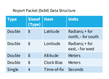
The Trimble Standard Interface Protocol (TSIP) allows you to control the GPS receiver and set GPS configuration parameters.
Trimble标准接口协议(TSIP)是一种用于控制GPS接收器和设置GPS配置参数的协议。
Example ASCII Serial Data: NMEA-0183
消息格式:$IDMSG,D1,D2,D3,D4,…,Dn*CS\r\n
• $ denotes the start of a message
• ID is a two letter mnemonic to describe the source of data, e.g. GP signifies GPS
• MSG is a three letter mnemonic to describe the message content.
• Commas are used to delaminate the data fields.
• Dn represents each of the data fields.
• * is used to separate the data from the checksum.
• CS contains two ASCII characters representing the hex value of the checksum.
• \r\n is the carriage return character followed by the new line character to denote
the end of a message.
其中,$表示消息的开始,ID是一个两个字母的助记符,用于描述数据源(例如GP表示GPS),MSG是一个三个字母的助记符,用于描述消息内容。逗号用于分隔数据字段,Dn代表每个数据字段。星号用于将数据与校验和分隔开来。CS包含两个ASCII字符,表示校验和的十六进制值。\r\n是回车符和换行符,用于表示消息结束。
NMEA 0183接口标准在全球许多行业领域使用。该标准定义了4800波特串行数据总线的电信号要求、数据传输协议和时间以及特定的句子格式
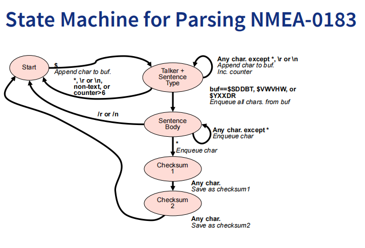
当状态机处于Start状态时,它等待接收到一个字符。如果接收到的字符是’$’,则状态机将切换到Talker状态。否则,它将保持在Start状态。 当状态机处于Talker状态时,它等待接收两个字母作为数据源标识符,并将其存储在缓冲区中。一旦接收到两个字母,状态机将切换到Sentence Type状态。 当状态机处于Sentence Type状态时,它等待接收三个字母作为消息类型标识符,并将其存储在缓冲区中。一旦接收到三个字母,状态机将切换到Sentence Body状态。 当状态机处于Sentence Body状态时,它等待接收逗号分隔的数据字段,并将每个字段存储在缓冲区中。一旦接收到星号(’*’),则表示消息体已经结束,并且校验和即将开始。此时,状态机将切换到Checksum 1 状态。 当状态机处于Checksum 1 状态时,它等待接收校验和的第一个十六进制字符,并将其存储在缓冲区中。一旦接收到第一个字符,则会切换到Checksum 2 状态。 当状态机处于Checksum 2 状态时,它等待接收校验和的第二个十六进制字符,并将其存储在缓冲区中。一旦接收到第二个字符,则状态机将计算校验和并检查其是否正确。如果校验和正确,则状态机将传递缓冲区中存储的完整消息给下一个处理步骤。否则,它将丢弃该消息并重新开始解析过程
Asynchronous / Synchronous serial (USART) Communications
STM32f401 features
STM32F401是一款微控制器,它包含了多个通信接口,其中之一就是USART(Universal Synchronous/Asynchronous Receiver/Transmitter)。USART是一种通用的同步/异步收发器,可以实现全双工通信。它支持NRZ标准格式
• Full duplex, asynchronous communications==全双工,异步==
• NRZ standard format (Mark/Space)用NRZ来传号和传空
• Configurable oversampling method by 16 or by 8 to give flexibility between speed and clock tolerance
可以通过16或8的过采样方法进行配置,以在速度和时钟容差之间提供灵活性。过采样是指在接收数据时对信号进行多次采样,以提高数据传输的可靠性。当使用16倍过采样时,USART会对输入信号每个bit进行16次采样,并将这些采样值平均后得到一个结果。这种方法可以提高数据传输的可靠性,但会降低通信速度。相反,当使用8倍过采样时,USART只对输入信号进行8次采样,并将这些采样值平均后得到一个结果。这种方法可以提高通信速度,但会降低数据传输的可靠性。因此,在配置USART时可以根据具体应用场景的需要选择16倍或8倍过采样方法,以在速度和时钟容差之间取得最佳平衡点。
• Fractional baud rate generator systems
• Programmable data word length (8 or 9 bits) Data word的长度可以设置为8bits或者9bits
• Configurable stop bits - support for 1 or 2 stop bits 可以设置stop bits的长度,1或2 bit
• Parity control
• Four error detection flags
• Ten interrupt sources with flags
• Synchronous mode
• Hardware flow control mode
USART区块图
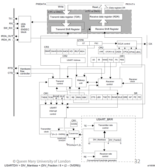
USART modes
Normal mode-TX pin and RX pin are used:
• RX: Receive Data Input is the serial data input
• TX: Transmit Data Output. When the transmitter is disabled, the output pin returns to its I/O port configuration. When the transmitter is enabled and nothing is to be transmitted, the TX pin is at high level.
当发送器被禁用时,输出引脚会返回到其I/O端口配置状态。当发送器被启用且没有要传输的数据时,TX引脚处于高电平状态。
Synchronous mode- CLK pin is used in addition to Tx and RX
除了TX和RX引脚之外,还需要使用CLK引脚。在这种模式下,数据传输是由一个显式的时钟信号控制的,这个时钟信号会与数据信号一起传输。
Hardware flow control mode
- CTS:clear to send,有效电平为低(阻断发送)
- RTS:用来指示USART以及准备好接收数据了,有效电平为低
Software Structure
通信和程序是异步的 - 不知道程序会执行什么代码【不知道什么时候收到消息】
- 不知道下一个item什么时候来
- 不知道当前的item什么时候完成传输
- 不知道有没有error发生
Need to synchronize between program and serial communication
interface somehow. Two options:
Polling:
• Wait until data is available
• Simple but inefficient of processor time
Interrupt:
• CPU interrupts program when data is available
• Efficient, but more complex
Serial Communications and Interrupts
Want to provide multiple threads of control in the program
需要==一个主线程,三个ISR==
• Main program (and subroutines it calls)
• Transmit ISR – executes when serial interface is ready to send another character
• Receive ISR – executes when serial interface receives a character
• Error ISR(s) – execute if an error occurs
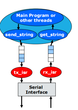
Need a way of buffering information between threads
• Solution: circular queue with head and tail pointers(循环队列)
• One for TX, one for RX
Code to Implement Queues
Enqueue(入队列) at tail: tail is the index of the next free entry
Dequeue (出队列)from head: head is the index of the item to remove
==队尾写新,队头读取==
Queue size is initialised and stored in size
• One queue per direction(TX RX各有一个队列)
• TX ISR unloads tx_q
• RX ISR loads rx_q
Need to wrap pointer at end of buffer to make it circular,
• Use % (modulus, remainder) operator if queue size is not power of two
假设队列大小为10,那么在enqueue操作中,可以使用以下代码来更新尾指针:
tail = (tail + 1) % 10;
• Use & (bitwise and) if queue size is a power of two
如果队列大小是2的幂,例如16,则可以使用以下代码来更新尾指针:
tail = (tail + 1) & 15;
- ==判断队列空==:
tail == head - ==判断队列满==:
(tail + 1) % size == head
Defining and initializing Queues
typedef struct {
uint8_t *data; //!< Array of data, stored on the heap.
uint32_t head; //!< Index in the array of the oldest element.
uint32_t tail; //!< Index in the array of the youngest element.
uint32_t size; //!< Size of the data array.
} Queue;
int queue_init(Queue *queue, uint32_t size) {
queue->data = (uint8_t*)malloc(sizeof(uint8_t) * size);
queue->head = 0;
queue->tail = 0;
queue->size = size;
// If malloc returns NULL (0) the allocation has failed.
return queue->data != 0;
}判断是否为满
int queue_is_full(Queue *queue) {
return ((queue->tail + 1) % queue->size) == queue->head;
}
int queue_is_empty(Queue *queue) {
return queue->tail == queue->head;
}
入队& 出队
使用queue_enqueue函数将要发送的数据存储在队列中,然后在tx_isr中从队列中读取数据并发送到USART。类似地,可以使用rx_isr从USART接收数据,并使用queue_dequeue函数将接收到的数据存储在uint8_t item中。
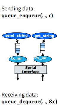
tx 入队
int queue_enqueue(Queue *queue, uint8_t item) {
if (!queue_is_full(queue)) {
queue->data[queue->tail++] = item;
queue->tail %= queue->size;
return 1;
} else {
return 0;
}
}
uint8_t 无符号8位整数 通常用于存储字节数据
rx出队
int queue_dequeue(Queue *queue, uint8_t *item) {
if (!queue_is_empty(queue)) {
*item = queue->data[queue->head++];
queue->head %= queue->size;
return 1;
} else {
return 0;
}
}
Control registers
USART_CR1

UE: USART使能位。当该位为1时,USART才能正常工作。
M: 字长位。当该位为0时,数据帧长度为8位;当该位为1时,数据帧长度为9位。
PCE: 奇偶校验使能位。当该位为1时,启用奇偶校验;当该位为0时,禁用奇偶校验。
PS: 奇偶校验选择位。当PCE=1时,PS=0表示选择偶校验;PS=1表示选择奇校验。
TE: 发送使能位。当该位为1时,允许发送数据。 - RE: 接收使能位。当该位为1时,允许接收数据。
OVER8: 过采样率选择位。当OVER8=0时,使用16倍过采样率;当OVER8=1时,使用8倍过采样率。
PEIE: 它的全称是Parity Error Interrupt Enable。当PEIE位被设置为1时,如果接收到的数据帧出现奇偶校验错误,将会产生一个奇偶校验错误中断。
USART_CR2

- ADD[3:0]: 地址位。当LINEN=1时,ADD[3:0]表示从机地址;当LINEN=0时,ADD[3:0]表示节点地址。
- LBDL: LIN波特率检测长度位。当LINEN=1时,LBDL=0表示检测10个比特时间;LBDL=1表示检测11个比特时间。
- LBDIE: LIN波特率检测中断使能位。当LINEN=1且LBDIE=1时,在检测到LIN波特率错误时会产生一个中断。
- STOP[1:0]: 停止位长度位。STOP[1:0]=00表示使用1个停止位;STOP[1:0]=01表示使用0.5个停止位;STOP[1:0]=10表示使用2个停止位;STOP[1:0]=11保留。
- CLKEN: 时钟使能位。当该位为1时,允许外部时钟输入到USART。 - CPOL: 时钟极性选择位。当CLKEN=1时,CPOL为串行同步模式下的时钟极性选择位。
- CPHA: 时钟相位选择位。当CLKEN=1时,CPHA为串行同步模式下的时钟相位选择位。
Status register: USART_SR

- PE: 奇偶校验错误标志位。当接收到的数据帧出现奇偶校验错误时,该位被置为1。
- FE: 帧错误标志位。当接收到的数据帧出现帧错误(即停止位不正确)时,该位被置为1。
- NF: 噪声检测标志位。当接收到的数据帧中出现噪声时,该位被置为1。
- ORE: 溢出错误标志位。当接收缓冲区溢出时,该位被置为1。
- IDLE: 空闲线路状态标志位。当接收线路空闲一段时间后,该位被置为1。
- RXNE: 接收缓冲区非空标志位。当接收缓冲区中有未读取的数据时,该位被置为1。
- TC: 传输完成标志位。当发送数据完成后(包括最后一个停止位),该位被置为1。
- TXE: 发送缓冲区空标志位。当发送缓冲区为空时,该位被置为1。
Baud rate register: USART_BRR

USART Character description
• Word length (depends on M in USAR_CR1)
• TX pin is in low state during the start bit. It is in high state during the stop bit
• Idle character**:** an entire frame of “1”s
• Break character: receiving “0”s for a frame period
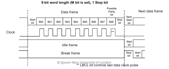
USART Transmitter
当【USART_AR1中的】TE设定后,在transmit shift register中的数据会输出到TX上(LSB先出)
USART_DR(TDR)用于缓存内部总线和发送移位寄存器之间的数据
写入USART_DR(TDR)时将TXE(Transmit buffer empty)标清除。
TXE set by HW if:
• Data moved from TDR to the shift register- Data TX started
• TDR register is empty.
• Next data can be written in the USART_DR register
USART_DR是一个数据寄存器,用于缓存接收和发送的数据。具体来说,当接收到一个字符时,该字符会被存储在USART_DR寄存器中;当发送一个字符时,该字符会从USART_DR寄存器中读取并传到发送移位寄存器中。
在空闲状态时**,传送线为逻辑“1”状态,而数据的传送总是以一个起始位“**0*”开始,所以当接收器检测到一个从“*1*”向“*0*”的跳变时,便视为可能的起始位*,*传送线为逻辑“*1*”状态,而数据的传送总是以一个起始位“*0*”开始,所以当接收器检测到一个从“*1*”向“*0****”的跳变时,便视为可能的起始位
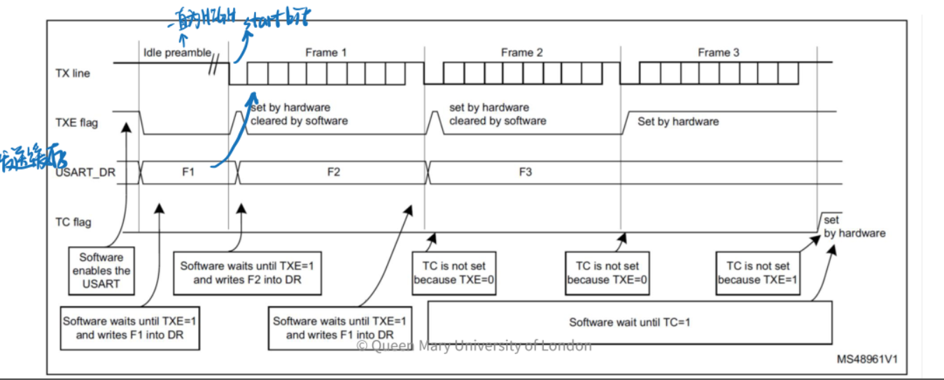
TXE告诉:总线空了、总线开始
USART Receiver
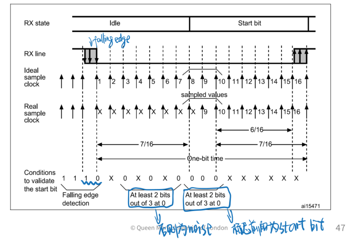
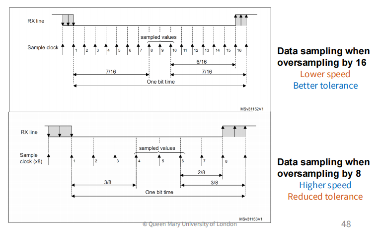
八倍过采样(一个bit采8个点),时钟容忍偏差会降低
在过采样过程中,每个数据位都会被重复采样多次,以提高数据传输的可靠性和精度。而在这些重复采样的数据位中,只有中间三个样值是必要的,因为它们可以提供足够的信息来确定数据位的值。
==用上图中间采样的三位来根据下表进行判断==,用于噪声误差检测和字符接收
当接收器在预期时间内未能识别到停止位(stop bit)时,就会发生帧错误,并且USART_SR寄存器中的FE位会被设置为1。FE位通过USART_SR寄存器读操作和USART_DR寄存器读操作复位。
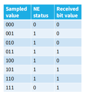
中间的都是noise
USART Baud Rate generation
The baud rate for Rx and TX are both set to the same value as programmed in the Mantissa and Fraction values of USARTDIV in USART_BRR.

OVER8在使用16 oversampling的时候设为0;当使用8 oversampling的时候设为1
USARTDIV是一个在USART_BRR寄存器上编码的unsigned fix number。
USART_BRR:(靠近MSB)前12位为Mantissa;后4位为Fraction
USART_CR1中的OVER8定义过采样率

得到4位的Fraction后,用Fraction的十进制数除以16得到fraction所表示的小数
左边例子:
- 0x1BC转为二进制为11011 1100,取前五位为Mantissa,后四位为Fraction【永远用四位为Fraction,是固定的,最多12位表示整数】
The lower the CPU clock the lower the accuracy for a particular baud rate.
USART Parity check
• Parity control = generation of parity bit in transmission and parity checking in reception.
• Enabled by setting the PCE bit in the USART_CR1.
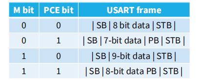
SB:开始位 STB:结束位 PB:校验位
M控制 9比特(1) 8比特(0)
PCE控制是否启用PB(包含在设定的比特数之中)
Even parity: obtain an even number of “1s” inside the frame made of data bits and the parity bit. E.g.: data=00110101; 4 bits set=> parity bit will be 0 (PS bit in USART_CR1 = 0).
Odd parity: obtain an odd number of “1s” inside the frame made of data bits and the parity bit. E.g.: data=00110101; 4 bits set => parity bit will be 1 (PS bit inUSART_CR1 = 1).
