08-I2C
I2C
a Bus-oriented Solution
I2C接口和协议:确保消息可以发送从一个设备到另一个选定的目标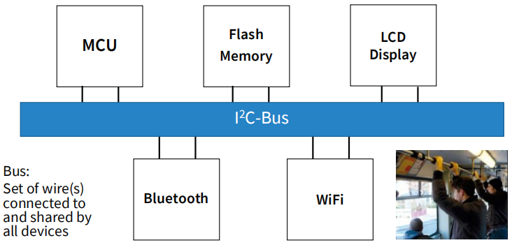
典型I2C配置方案
Master作为发送端
- 初始发送
- 创建CLK
- 结束发送
Slave作为接收端
- 监听
- 等待Master分配地址
- 接收数据
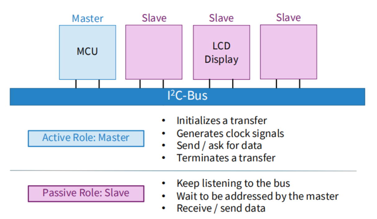
在I2C总线上,只有主设备才能启动和控制数据传输。从设备则被动地等待主设备的指令并响应
Transfer Procedure

- 微控制器启动传输。
- 微控制器将LCD地址设置为0x27。
- 微控制器向LCD发送写入指令。
- LCD确认来自微控制器的调用。
- 微控制器向LCD发送数据(主-发射机和从-接收机)。
- LCD确认接收到的数据。
- 微控制器停止传输。
Transfer Protocol
数据传输格式通常是8位字节。每个字节都由一个起始位、8个数据位、一个可选的奇偶校验位和一个或2个停止位组成。
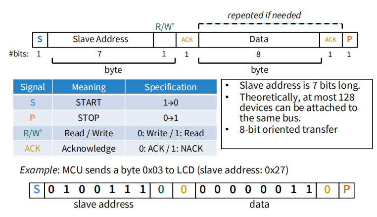
Slave address is 7 bits long.
Theoretically, at most 128 devices can be attached to the same bus
Address后面的一位叫
R/W,用来表示是读取还是写,0表示写,1表示读数据总长为一个字节,8个bits,每一个字节就要回一个ACK
在I2C总线上,主设备和从设备之间的通信是通过交替使用SDA和SCL线来实现的,并且每个字节都有一个相应的ACK或NACK信号来确认是否成功接收。
I2C Wires: SDA & SCL
SDA是数据信号线,用于在主设备和从设备之间传输数据。SCL是时钟信号线,用于同步数据传输。

Serial communications - ONE bit is sent at a time.
There are 3 elements in serial comm.: START, BIT, STOP
SDA: Serial data - transmits actual address/data bits.
SCL: Serial clock - synchronises the data.
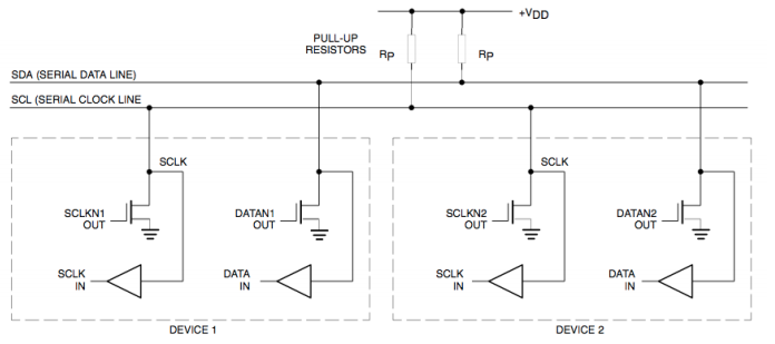
• Both are pulled up to supply VCC (‘1’) through resistors.
• Can be pulled down to Gnd (‘0’) by the devices.
在I2C总线上,SDA和SCL信号线都通过电阻器上拉到VCC电源电压(通常为5V或3.3V),以保持高电平状态。当设备需要将信号拉低时,它们可以通过将SDA和SCL连接到地(GND)来拉低这些信号线
两个线在默认情况下都是高电平【因为连接到了Vcc】【空闲时都是HIGH】
==SDA和SCL都是bi-directional的==
I2C Electrical Details
Both SDA and SCL are bi-directional.
• Uses open collector/drain outputs 使用开路集电极/漏极输出
• Lines float HIGH unless an output goes LOW.
正常情况下,这些信号线处于高电平状态(即浮空),除非某个设备需要将其拉低以发送数据。
SDA & SCL: START, BIT, STOP
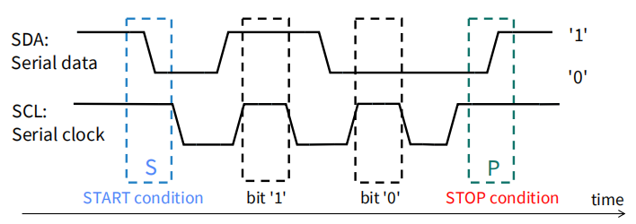
• START and STOP must be generated by the master.
START 和 STOP 都必须是由Master来创建
- START:SCL为1的情况下,检测到SDA中的下降沿
- STOP:SCL为1的情况下,检测到SDA中的上升沿
• Data bit is valid only when SCL is ‘1’.
SCL is also generated by the master.
时钟频率决定了数据传输速率
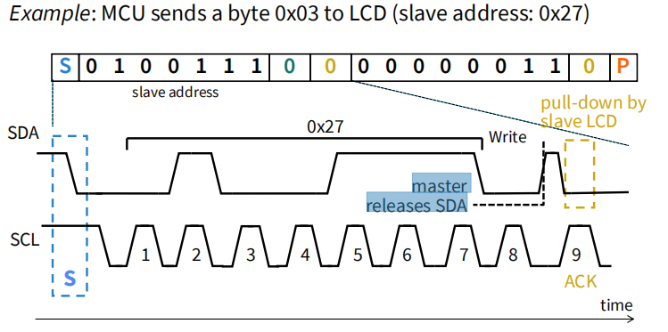
图中为发送address的例子,最后一位ack之前master必须releaseSDA,这样SDA回到默认的高电平状态(为了让接收机拉低以表示ack)
Acknowledge Signal (ACK)
• ACK takes place after every byte is sent.
It signals to the master/transmitter that the byte was successfully received.
发射器释放SDA线,因此接收器可以将SDA线拉低(‘0’)。
If SDA remain ‘1’, it is a Not acknowledge signal (NACK). Possible scenarios:
No receiver on the bus
The receiver is unable to receive or transmit (not ready)
During the transfer, the receiver does not understand the data / cannot receive any more data bytes.
A master-receiver uses NACK to signal the end of the transfer to the slave-transmitter (then generates a STOP)如果主设备向从设备发送了一系列字节,并且从设备无法正确接收其中的某个字节,则它可以发送一个Not Acknowledge (NACK)信号来通知主设备停止传输。这可以避免在总线上出现死锁或其他错误情况。当主设备接收到NACK信号时,它会生成一个STOP条件来结束传输。
优缺点
优
Simple and easy to implement
ICs can be attached or detached without affecting other circuits.
There are fewer I/O pins & fewer PCB tracks.
缺点:
- 最慢的I2C设备支配着总线性能,尤其是时钟经常被拉长。【木桶效应】
- 7位从地址允许(理论上)在同一总线上最多128个设备。
- 因为I²C是一个共享总线,一个故障设备会挂起整个总线。例如,它保持拉SDA低(‘0’),主机不能产生START/STOP。
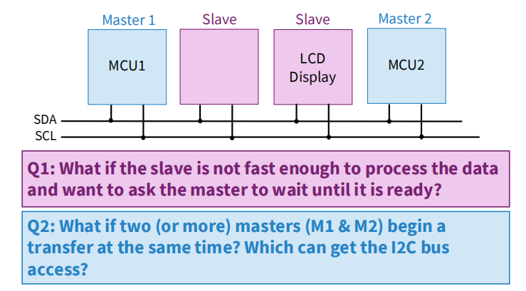
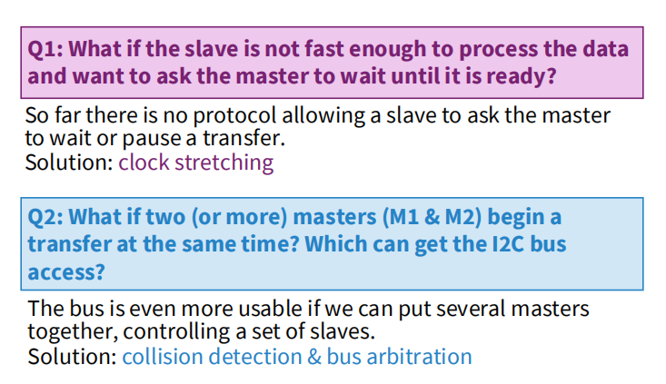
Clock Stretching
Clock stretching: slave pulls down SCL to ‘0’ while it is not ready for more data.
从设备在接收到数据时,如果还没有准备好接收更多的数据,它可以将SCL线拉低来暂停时钟信号的传输,这样主设备就发不出来新数据。这可以让从设备有足够的时间来处理之前接收到的数据。主设备必须等待SCL线恢复到高电平后才能继续发送数据。在等待期间,主设备必须保持SDA线保持稳定状态以避免出现错误。
Master has to wait until SCL = ‘1’ again, and continues to send data after an additional minimum buffer time (say 4 μs).
主设备必须等待一段时间(称为buffer time)以确保从设备已经准备好接收更多的数据。这个buffer time通常是4微秒左右。
Bus Arbitration 总线仲裁

如果一个设备正在发送数据并且检测到SDA和SCL线上的信号与它发送的信号不匹配,则该设备将停止发送数据并等待一段时间后再次尝试发送。
总线判优:选取与总线发送数据相同的DATA
10-bit Addressing
- 10-bit addressing使得可用地址变多
- 用10-bit addressing的和用7-bit addressing的可以混在一起用
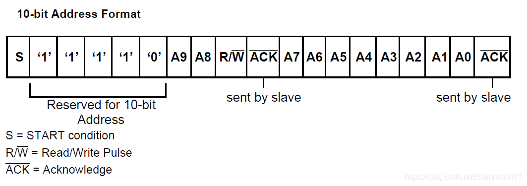
- 10位从地址由START条件(S)或重复START条件(Sr)后的后两个字节组成。

Combined Format & Repeated Start
If the master wants to change the direction of transfer, then it simply addresses the slave again using a new R/W’ with another START signal. (instead of a STOP)
This is usually called the “repeated START” (Sr)

A master-transmitter addresses and sends a byte to a slave-receiver. Then it generates a repeated START and change the direction. The slave then becomes a transmitter and sends data afterwards.
Reserved Address
在I2C总线协议中,每个设备都有一个唯一的7位地址,其中一些地址被保留用于特殊目的。
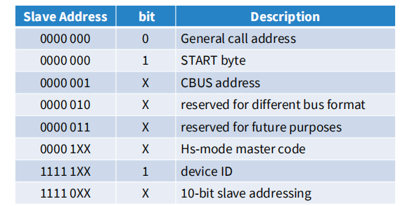
bit是R/W
如果知道保留地址永远不会用于其预期目的,则可以将保留地址用于从地址。
General Call 广播
Address “00000000” is reserved for general call: broadcasts to all devices connected to the bus.
从设备可以:
•用NACK忽略这个通用调用(什么都不做)
•对召唤做出回应和承认,并成为一个接收者。
I2C总线协议中,如果有多个设备响应主设备的请求,这种情况被称为wired-AND。在这种情况下,主设备不知道响应请求的设备数量。因此,设计系统时需要确保每个请求只有一个设备响应或使用其他方法(例如仲裁)来解决冲突并确保总线上的正确通信
The second byte in this general call determines the action requested by the master, including Software reset, START byte (for MCU transfer), Bus clear, Device ID
第二个字节用于指定主设备请求的操作类型。这些操作类型包括软件复位、START字节(用于MCU传输)、总线清除和设备ID等。
Programming I2C in Cortex M3/M4
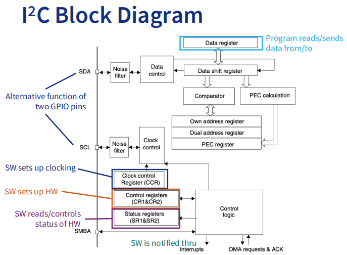
Slave Mode
On default, the I2C interface works in slave mode.
• The peripheral input clock must be programmed in the I2C_CR2 register in order to generate correct timings. 在I2C_CR2寄存器中设置外设输入时钟
标准模式下,SCL时钟频率最高为100 kHz时,外设输入时钟频率必须至少为2 MHz
It match the slave address in OAR1. When matched it generates:
• an acknowledge pulse if the ACK bit is set
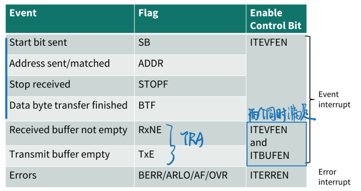
• the ADDR bit is set by hardware and an interrupt is generated if the ITEVFEN bit is set.
硬件会将ADDR位设置,并且如果ITEVFEN位被设置,则会生成一个中断
Own Address Register
自身地址寄存器。在I2C从设备模式下,当主设备向从设备发送数据时,主设备需要知道从设备的地址才能正确地将数据发送到该从设备。因此,在OAR1寄存器中设置了从设备的地址。
The TRA bit indicates whether the slave is in Receiver or Transmitter mode.
TRA是I2C接口的一个位,它是指“Transmitter/Receiver Address bit”,即传输器/接收器地址位。在I2C从设备模式下,当主设备向从设备发送数据时,该位指示从设备当前处于接收器模式还是传输器模式。如果该位被设置为1,则表示从设备当前处于传输器模式;如果该位被设置为0,则表示从设备当前处于接收器模式。
Transmitter
硬件通过内部移位寄存器从DR寄存器发送字节到SDA线。
当从设备向主设备发送数据时,它会将SCL线拉低,直到ADDR(从设备的地址匹配)被清除并且DR(从设备)被填充了要发送的数据(在下面的EV1和EV3-1期间)。这会强制主设备等待数据。当从设备接收到来自主设备的应答脉冲时,如果ITEVFEN和ITBUFEN位都被设置,则硬件会设置TxE位并产生中断。
- ITBUFEN和ITEVFEN是I2C总线上的中断控制寄存器位。它们用于控制I2C总线上的中断事件。

EV3-1表示数据寄存器(DR)为空,软件将Data1写入DR。这意味着主设备已经向从设备发送了地址,并且从设备已经确认地址匹配。此时,主设备可以将数据写入DR并开始传输数据。EV3表示数据寄存器(DR)为空,但是移位寄存器正在传输数据。这意味着主设备已经开始向从设备发送数据,并且正在通过移位寄存器逐位传输字节。
Receiver
HW通过内部移位寄存器从SDA线接收字节到DR寄存器。
After each byte the interface generates in sequence:
- ACK设置为1表示确认脉冲
RxNE位由硬件设置,如果设置了ITEVFEN和ITBUFEN位,则会产生一个Interrupt。
如果设置了RxNE,并且在下一次数据接收结束之前没有读取DR寄存器中的数据,则设置BTF位,将SCL拉低,使HW等待,直到从I2C_DR寄存器读取BTF清除。【确保Slave接收到了每一个bit】

接收完最后一个Byte之后,Master会发一个STOP,在HW检测到STOP bit后会设置STOPFbit。如果ITEVFEN=1的话,还会产生一个Interrupt
Master Mode
HW启动数据传输并产生时钟信号,其初始化顺序如下:
- 在
I2C_CR2中编写Peripheral input clock - Configure the clock control registers
- Configure the rise time register
- Program I2C_CR1 registers to enable
- Set the START bit in I2C_CR1
HW检查SCL是否有任何stretching
设置START bit会导致 HW产生一个START(a Restart),并切换到Master模式。
- START bit由HW设置,当
ITEVFEN=1时产生中断。
Then it waits for a read of the SR1 (from SW) and then a write to DR with the slave address.
- HW enters transmitter mode if R/W’ (LSB in DR) = 0;
- HW enters receiver mode otherwise
只要发送地址字节,硬件就会设置ADDR bit,如果ITEVFEN=1就会产生interrupt。
Transmitter
- SW清除ADDR并向DR加载数据。
- 然后HW向SDA发送bytes。
- 当slave发送ACK时,
TxE位由硬件设置,如果ITEVFEN=ITBUFEN=1【两个同时为1】则产生中断。 - SW设置STOP bit,产生STOP signal。
- 然后HW回到slave模式。

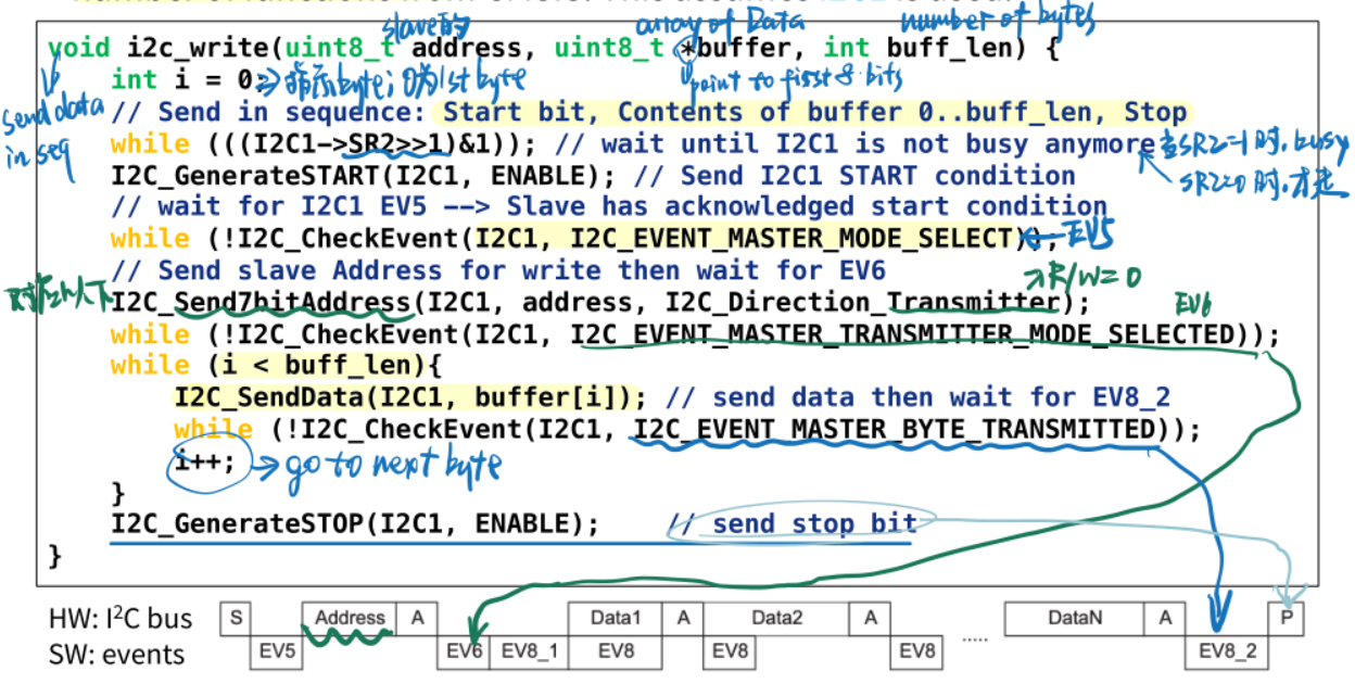
Master: i2c_write()
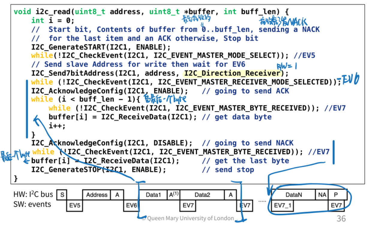
利用CMSIS的一些函数,用C代码研究基本轮询版本的主发射机。这里假设使用了I2C1【有很多I2C可以用,这里只用了一个】。
Receiver
- HW通过内部移位寄存器从SDA线路接收字节到DR。
- After each byte the interface generates in sequence:
- An acknowledge pulse if the ACK bit is set
- The RxNE bit is set and an interrupt is generated if
ITEVFEN=ITBUFEN=1.
- 等待从SW读取数据:如果RxNE=1,并且DR寄存器中的数据没有被读取,则设置BTF位将SCL拉低,并等待直到DR寄存器中的BTF被读取清除。

Master: i2c_read()
Error Conditions
A quick summary on possible errors raised by I2C interface HW.
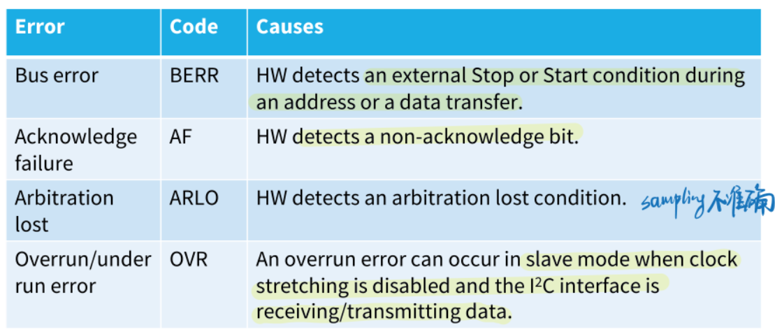
在所有情况下,都会设置相应的错误位,并产生一个interrupt(==前提:如果中断错误使能==ITERREN=1)。
C Interrupts
