05-GPIO
General Purpose Input Output
Input/Output Strategy of microprocessors
Memory Mapped I/O (MMIO)
• Main memory and peripheral I/O devices map into one single address space
主存储器和外设I/O设备映射到一个地址空间
Port Mapped I/O (PMIO)
Peripherals have separate address space from main memory
外设与主存有独立的地址空间
对I/O有特殊的CPU指令
Memory-Mapped I/O
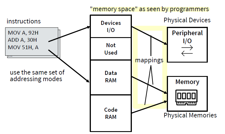
Pros 优点
- No extra external circuitry required for I/O access - simpler & cheaper.
- Every instruction which can access memory can be used to manipulate an I/O device.
Cons 缺点
- Uses up main memory space for peripherals
Port-Mapped I/O
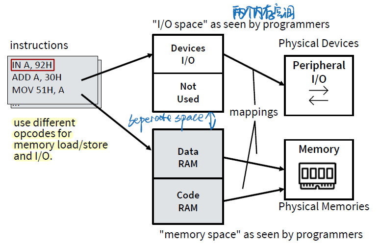
Pros
- Separate I/O and memory access
- Allows full memory space to be used for RAM
- Obvious to see when I/O occurs in program code because of special I/O functions
Cons
- Introduces complexity to internal circuits 更贵
- Special I/O functions harder to support for higher level language compilers
- More instructions are required to accompolish the same task, e.g. test one bit on I/O
Input/Output ==Pins & Ports==
Most of embedded microprocessors have I/O memory-mapped
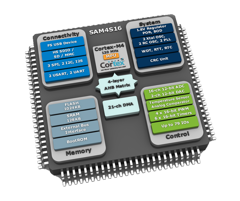
One key feature of a microcontroller is the versatility built into the input/output (I/O) circuits.
- Microprocessor designs, on the other hand, must add additional chips to interface with external circuitry.
Microcontroller 有 IO
Microprocessor 没有 IO
The function a pin performs can be easily programmed.
General Purpose Input Output (GPIO)
Basic Concept
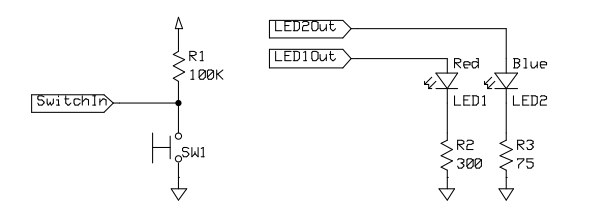
• GPIO = General-purpose input and output (digital)
• Input: program can determine if input signal is a 1 or a 0
• Output: program can set output to 1 or 0
• Can use this to interface with external devices
• Input: switch
• Output: LEDs
example
STM32家族的微控制器有几个数字端口,称为GPIO1, GPIO2, GPIO3,…
每个端口有16位,因此有16个电引脚。引脚被称为Px_y,其中x是端口名称(1,2,3,…),y是位(0,1,…)15)。the pin P2_3 is the bit 3 of the port 2.
port是指一组GPIO引脚,通常由多个引脚组成。每个port都有一个名称(例如GPIO1、GPIO2等),并且每个port中的每个引脚都有一个唯一的编号(例如P2_5)。可以将port视为一组相关联的GPIO引脚,它们通常用于执行相似的任务。
Each PIN can be configured as Input or Output
Some PINs has also an alternate function, related to a peripheral
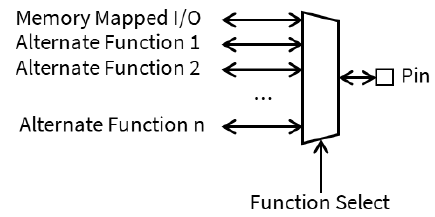
GPIO Alternative Functions
Pins may have different features
• To enable an alternate function, set up the appropriate register
Pins may also have analogue paths for ADC / DAC etc.
某些GPIO引脚可能具有模拟信号路径,可以用于连接模拟到数字转换器(ADC)或数字到模拟转换器(DAC)等外设。这意味着这些引脚可以用于读取或输出模拟信号,而不仅仅是数字信号。在使用这些引脚时,需要将它们配置为相应的模拟输入或输出,并使用适当的ADC或DAC外设进行读取或输出。
Advantages:
- Saves space on the package
- Improves flexibility
==GPIO Input Mode==
Ensure a known value on the input of a pin is left floating
For example, to get the switch SW1 to pull the pin to ground, we should enable the
pull-upIn
pull-upmode, the pin value isHIGHwhen SW1 is not pressedLOWwhen SW1 is pressed
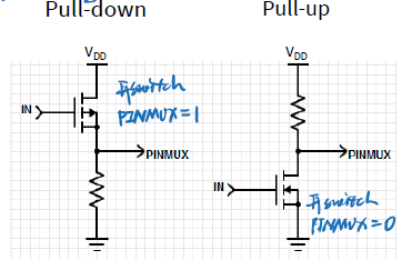
pull down
pressed switch PINMUX =1
not pressed switch PINMUX =0
pull up
pressed switch PINMUX =0
not pressed switch PINMUX =1
GPIO Output Mode
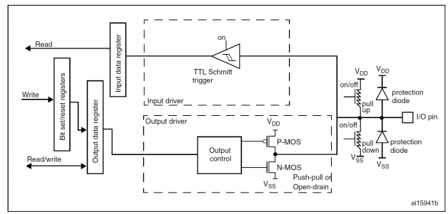
一个IOpin 输入电压以后,根据上拉还是下拉判断为0、1存到IDR寄存器
ODR输出数据时候输出到Output control,改写为对应电压再输出引脚
input的时候如何判断0 还是 1
- Input signal’s value is determined by voltage
- Input threshold voltages depend on supply voltage $V_{DD}$
- Excceding $V_{DD}$ or $GND$ may damage chip
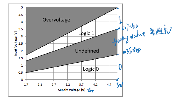

避免floating value区间
output的时候如何判断0 还是 1
Nominal(标准) output voltages
• 1: VDD-0.5 V to VDD
• 0: 0 to 0.5 V
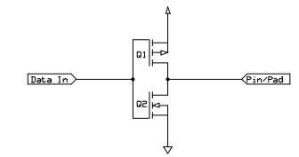
Note: Output voltage depends on current drawn by load on pin
- Need to consider source-to-drain resistance in the transistor

- Above values only specified when current < 5 mA (18 mA for high-drive pads) and VDD > 2.7 V
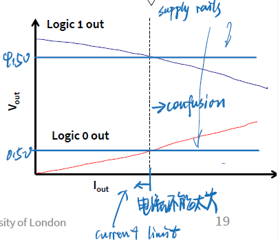
The ports are not capable of driving loads that require large currents.
i.e. the output current is often limited in range of tens of mA.
e.g. ARM Cortex-M-based MCUs, the maximum output current per pin is 5 mA.
If necessary, buffers should be added externally to make sure the current drained from the microcontroller is reasonable
Controlling the GPIO
GPIO Special Function Registers
配置CPU或外围设备中硬件操作的寄存器
Each general-purpose I/O port has:
4 x 32-bit configuration registers:
- GPIOx_MODER: configures each bit as input or output or other
- GPIOx_OTYPER: output type configuration (push-pull or open-drain)
- GPIOx_OSPEEDR: configures the maximum frequency of an output pin
- GPIOx_PUPDR: configures the internal pull-up or pull-down register
2 x 32-bit data registers:
- GPIOx_IDR: the input data register
- GPIOx_ODR: the output data register
1 x 32-bit set/reset register:
- GPIOx_BSRR: the bit set/reset register
1 x 32-bit locking register:
- GPIOx_LCKR : the bit lock register
2 x 32-bit alternate function selection register:
- GPIOx_AFRH
- GPIOx_AFRL.
Mode Register
偏移地址0x00

两个Bits为一组
MODER allows a programmer to define the functionality of a GPIO pin
Each pin has ==2 bits== that permits the following configurations:
00: Input (reset state)01: General purpose output mode10: Alternate function mode11: Analog mode
举例要把GPIO9进行设置为通用输出模式 则把19位18位 置为01
GPIOF ->MODER &= ~(3<<18);  //进行清零
GPIOF ->MODER |= 1<<18;     //进行配置
Pull-up/Pull-down register
偏移地址0x0C
P12 Pull-down
P0 Pull-up

PUPDR defines the presence of a pull-up or pull-down resistor (or none) at the GPIO pin
Each pin has ==2 bits== that permits the following configurations:
00: No pull-up/pull-down01: Pull-up10: Pull-down
举例将GPIO口设置为上拉 需要将19 18 位进行清零然后赋值01
GPIOF ->PUPDR   &=~(3<<18);
GPIOF ->PUPDR   |=1<<18;
IRD/ODR
偏移地址0x10/0x14
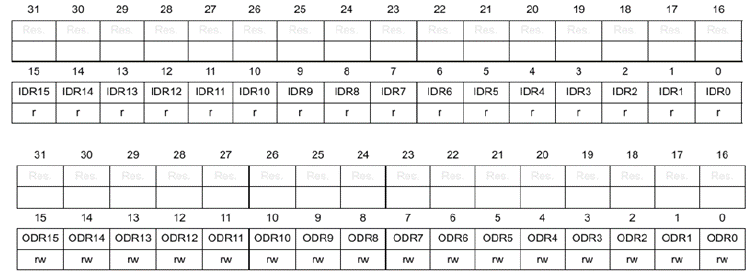
Data Input/Output is performed through the IDR and ODR registers
ODR可以对单独的位进行书写
Each pin is mapped to the specific bit, so ==only 16 bits are used in the registers==
CMSIS to access registers
查找和记住硬件控制寄存器的地址是很乏味的。
•相反,我们使用特殊的Clanguage支持。
CMSIS是Cortex微控制器软件接口标准(Cortex Microcontroller Software Interface Standard)
•Cortex微控制器软件接口标准CMSIS是一个独立于供应商的硬件抽象层,用于基于Arm®Cortex®处理器的微控制器。
Code Structure
- Main code talks to the drivers, producing easy to read and understand code
//Port 2, bit 6
gpio_set_mode(P2_5, Output)//设置- Drivers utilise CMSIS library and group relevant actions
port_struct->direction_reg = outputport_struct是一个指向GPIO端口结构体的指针,direction_reg是该结构体中的一个成员变量,用于控制端口的方向。
- CMSIS transforms memory mapped registers into C structs
#define PORT0 ((struct PORT*)0x2000030)0x2000030是GPIO端口的基地址,而PORT结构体是用于访问该端口的数据结构。通过将该地址强制转换为指向PORT结构体的指针,并将其定义为宏,可以方便地在代码中引用该GPIO端口,并使用类似于PORT0->direction_reg = output这样的语法来配置和控制该端口。
- Registers directly control hardware
- Hardware drives IO pins physically
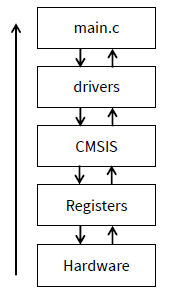
Drivers Layer: How It Works
void gpio_set(Pin pin, int value)- mask = 1 << pin index
2) tmp = port_struct->data_reg & ~mask (取mask的反)
3) tmp |= value << pin index
4) port_struct->data_reg = tmp
e.g. gpio_set(P2_5, 1) with PORT_DATA_REGISTER = 0b01010101
Create a mask for the bit we want to set (0b00100000)
为我们想要设置的位创建一个掩码
Invert the mask (0b11011111) to select all the other bits in the port data register,and save the status of the other bits (tmp = 0b01010101)
反转掩码(0b11011111)以选择端口数据寄存器中的所有其他位,并保存其他位的状态(tmp = 0b01010101)
保留寄存器中其他位的状态,而只修改要设置的那一位(与上补码)并把本位清零
- Move the new value of the bit into position, and or it with the new register value
(tmp = 0b01110101)
将改变的mark与原状态或起来(tmp = 0 b01110101)
- Write the new data register value out to the port (PORT_DATA_REGISTER =0b01110101)
将新的数据寄存器值写入端口(PORT_DATA_REGISTER =
0b01110101)
int gpio_get(Pin pin)- mask = 1 << pin index
2) tmp = port_struct->data_reg & mask (取mask)
3) tmp >>= pin index
4) return tmp
e.g. gpio_get(P2_5) with PORT_DATA_REGISTER = 0b01110101
将提取位设为1来提取。
- Create a mask for the bit we want to get (0b00100000)
- Select the bit in the port data register based on the mask (tmp = 0b00100000)
- Bitshift the value to produce a one or zero (tmp = 0b00000001)
- Return the value of the pin back to the user
C Interface: GPIO Configuration
/*! This enum describes the directional setup of a GPIO pin. */
typedef enum {
	Reset, //!< Resets the pin-mode to the default value.
	Input, //!< Sets the pin as an input with no pull-up or pull-down.
	Output, //!< Sets the pin as a low impedance output.
	PullUp, //!< Enables the internal pull-up resistor and sets as input.
	PullDown //!< Enables the internal pull-down resistor and sets as input.
} PinMode;
/*! \brief Configures the output mode of a GPIO pin.
* Used to set the GPIO as an input, output, and configure the
* possible pull-up or pull-down resistors.
* \param pin Pin to set.
* \param mode New output mode of the pin.*/
void gpio_set_mode(Pin pin, PinMode mode);/*! \brief Sets a pin to the specified logic level.
* \parampin Pin to set.
* \param value New logic level of the pin (0 is low, otherwise high).
*/
void gpio_set(Pin pin, int value);/*! \brief Get the current logic level of a GPIO pin.
* \param pin Pin to read.
* \return The logic level of the GPIO pin (0 if low, 1 if high).
*/
int gpio_get(Pin pin);Examples
Read a pushbutton and lit the LED
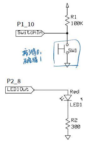
int main()
{
	// configure pin P1_10 as input
	gpio_set_mode(P1_10, Input);
	// configure pin P2_8 as output
	gpio_set_mode(P2_8, Output);
	// infinite loop
	for (1) {
		int PBstatus=gpio_get(P1_10);
		gpio_set(P2_8, !PBstatus); //低的为开灯
	}
}

//为啥这个不用设置上拉还是下拉
目标:如果开关SW1被按下,只亮红色LED1,如果没有按下,只亮蓝色led2
- 用
Pullup的话,SW1- 没按下 -> 1
- 按下 -> 0
用Pullup、Pulldown影响的是判断是否按下的语句。
gpio_set_mode(P_LED1, Output); // Set LED pins to outputs
gpio_set_mode(P_LED2, Output);
gpio_set_mode(P_SW, PullUp); // Switch pin to resistive pull-up
while (1) {
	if (gpio_get(P_SW)) {
		// Switch is not pressed (active low), turn LED1 off and LED2 on.
		gpio_set(P_LED1, 0);
		gpio_set(P_LED2, 1);
	} else {
		// Switch is pressed, turn LED2 off and LED1 on.
		gpio_set(P_LED2, 0);
		gpio_set(P_LED1, 1);
	}
}
GPIO in keil
导包:
#include "stm32f10x.h"
#include "platform.h"
#include "gpio.h"
设置模式
输出
gpio_set_mode(PA_0, Output);输入
gpio_set_mode(PA_1, PullUp);gpio_set_mode(PB_0, PullDown);一个端口输入输出
volatile int p, q;

//读取电平值
p = gpio_get(PA_13);
q = gpio_get(PA_14);

//设置电平值
gpio_set(PA_0, PIN_HIGN);
PIN_HIGH = 1;
PIN_LOW = 0;几个端口输入输出
gpio_get_range(PA_2, 4);gpio_set_range(Pinbase,count,value)基引脚,比特数,比特值
Toggle
变成相反的电平
gpio_toggle(PB_7);补充
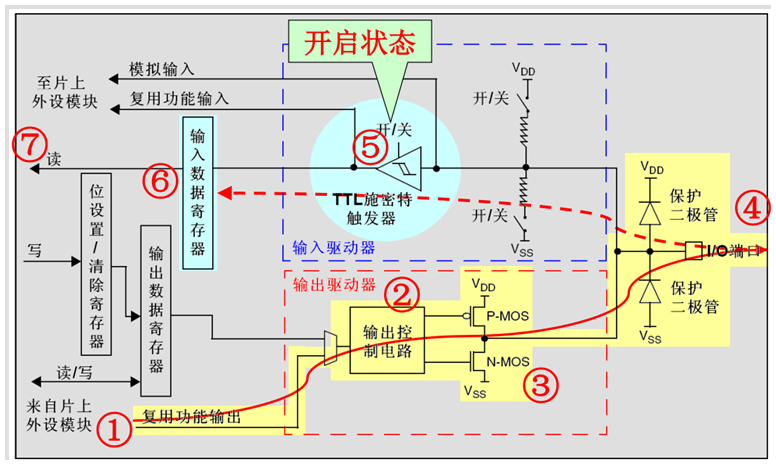
GPIO基本结构
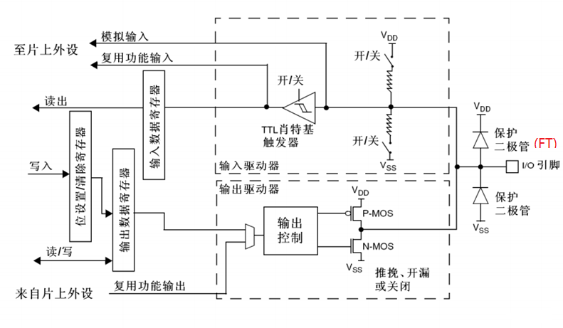
每个GPIO内部都有这样的一个电路结构,这个结构在本文下面会具体介绍。
这边的电路图稍微提一下:
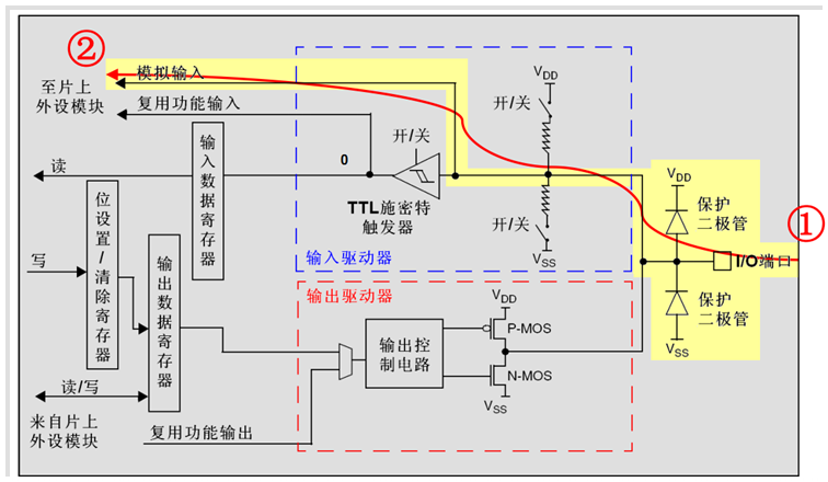
保护二极管:IO引脚上下两边两个二极管用于防止引脚外部过高、过低的电压输入。当引脚电压高于VDD时,上方的二极管导通;当引脚电压低于VSS时,下方的二极管导通,防止不正常电压引入芯片导致芯片烧毁。但是尽管如此,还是不能直接外接大功率器件,须加大功率及隔离电路驱动,防止烧坏芯片或者外接器件无法正常工作。
P-MOS管和N-MOS管:由P-MOS管和N-MOS管组成的单元电路使得GPIO具有“推挽输出”和“开漏输出”的模式。这里的电路会在下面很详细地分析到。
TTL肖特基触发器:信号经过触发器后,模拟信号转化为0和1的数字信号。但是,当GPIO引脚作为ADC采集电压的输入通道时,用其“模拟输入”功能,此时信号不再经过触发器进行TTL电平转换。ADC外设要采集到的原始的模拟信号。
这里需要注意的是,在查看《STM32中文参考手册V10》中的GPIO的表格时,会看到有“FT”一列,这代表着这个GPIO口时兼容3.3V和5V的;如果没有标注“FT”,就代表着不兼容5V。
GPIO工作方式
GPIO支持4种输入模式(浮空输入、上拉输入、下拉输入、模拟输入)和4种输出模式(开漏输出、开漏复用输出、推挽输出、推挽复用输出)。同时,GPIO还支持三种最大翻转速度(2MHz、10MHz、50MHz)。
每个I/O口可以自由编程,但I/O口寄存器必须按32位字被访问。
- GPIO_Mode_AIN 模拟输入
- GPIO_Mode_IN_FLOATING 浮空输入
- GPIO_Mode_IPD 下拉输入
- GPIO_Mode_IPU 上拉输入
- GPIO_Mode_Out_OD 开漏输出
- GPIO_Mode_Out_PP 推挽输出
- GPIO_Mode_AF_OD 复用开漏输出
- GPIO_Mode_AF_PP 复用推挽输出
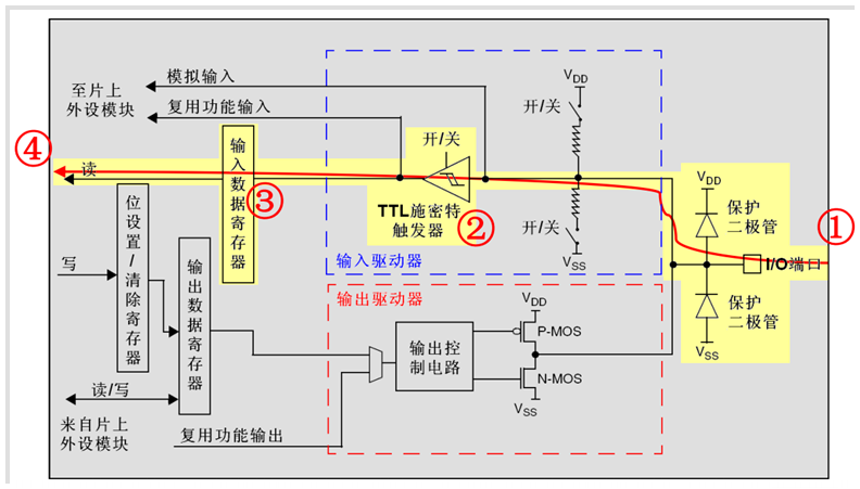
浮空输入模式
浮空输入模式下,I/O端口的电平信号直接进入输入数据寄存器。也就是说,I/O的电平状态是不确定的,完全由外部输入决定;如果在该引脚悬空(在无信号输入)的情况下,读取该端口的电平是不确定的。
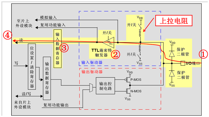
上拉输入模式
上拉输入模式下,I/O端口的电平信号直接进入输入数据寄存器。但是在I/O端口悬空(在无信号输入)的情况下,输入端的电平可以保持在高电平;并且在I/O端口输入为低电平的时候,输入端的电平也还是低电平。
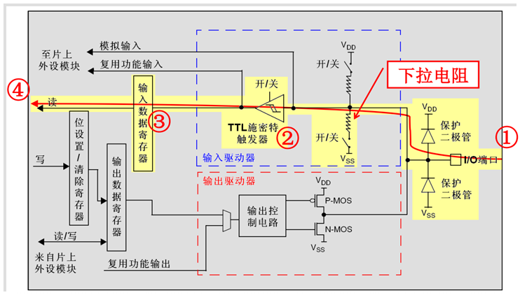
下拉输入模式
下拉输入模式下,I/O端口的电平信号直接进入输入数据寄存器。但是在I/O端口悬空(在无信号输入)的情况下,输入端的电平可以保持在低电平;并且在I/O端口输入为高电平的时候,输入端的电平也还是高电平。
模拟输入模式
模拟输入模式下,I/O端口的模拟信号(电压信号,而非电平信号)直接模拟输入到片上外设模块,比如ADC模块等等。
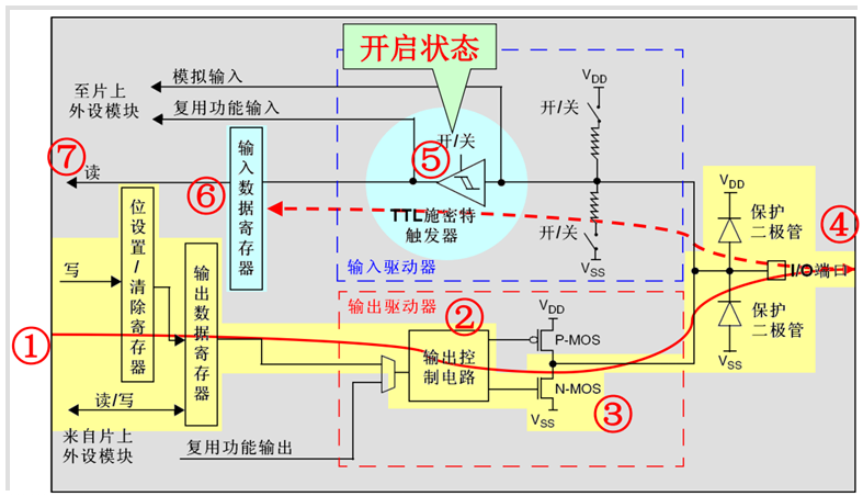
开漏输出模式
开漏输出模式下,通过设置位设置/清除寄存器或者输出数据寄存器的值,途经N-MOS管,最终输出到I/O端口。这里要注意N-MOS管,当设置输出的值为高电平的时候,N-MOS管处于关闭状态,此时I/O端口的电平就不会由输出的高低电平决定,而是由I/O端口外部的上拉或者下拉决定;当设置输出的值为低电平的时候,N-MOS管处于开启状态,此时I/O端口的电平就是低电平。同时,I/O端口的电平也可以通过输入电路进行读取;注意,I/O端口的电平不一定是输出的电平。
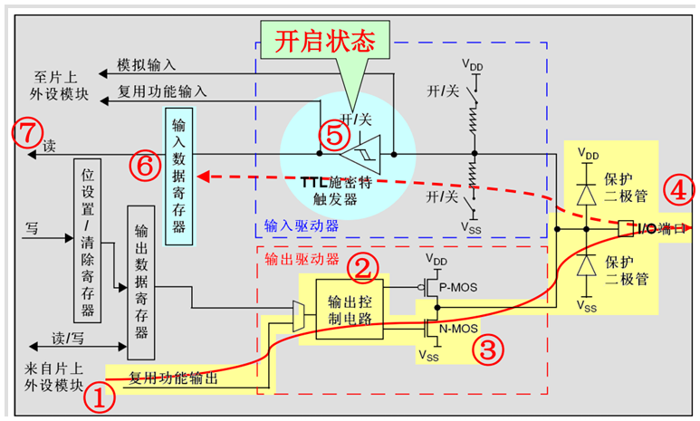
开漏复用输出模式
开漏复用输出模式,与开漏输出模式很是类似。只是输出的高低电平的来源,不是让CPU直接写输出数据寄存器,取而代之利用片上外设模块的复用功能输出来决定的。
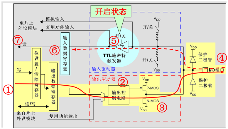
推挽输出模式
推挽输出模式下,通过设置位设置/清除寄存器或者输出数据寄存器的值,途经P-MOS管和N-MOS管,最终输出到I/O端口。这里要注意P-MOS管和N-MOS管,当设置输出的值为高电平的时候,P-MOS管处于开启状态,N-MOS管处于关闭状态,此时I/O端口的电平就由P-MOS管决定:高电平;当设置输出的值为低电平的时候,P-MOS管处于关闭状态,N-MOS管处于开启状态,此时I/O端口的电平就由N-MOS管决定:低电平。同时,I/O端口的电平也可以通过输入电路进行读取;注意,此时I/O端口的电平一定是输出的电平。
推挽复用输出模式
推挽复用输出模式,与推挽输出模式很是类似。只是输出的高低电平的来源,不是让CPU直接写输出数据寄存器,取而代之利用片上外设模块的复用功能输出来决定的。

